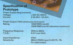
They 100w was suggested by someone on here some time ago but I now think that they could have calculated the 60.1v based on the 110v USA voltage and not our 240v ? Does that make sense Tom ?100 W could be a typo or it could be due to the topology of the amp.
Why not measure it? Run a 400 Hz sine wave into the amp and raise the volume until the amp clips. Then turn the volume down just enough that the amp provides a clean sine wave output. You can do this with a function generator and an oscilloscope. If you don't have a function generator, use this online one: https://www.wavtones.com/functiongenerator.php If you don't have a scope, plot the output voltage versus the input voltage as you increase the input voltage. You'll find Vout/Vin is a straight line until it hits a knee. That knee is when the amp clips. Take the last output voltage before the knee and do P = E^2/R. That'll give you the output power.
Ideally load the amp with an 8 Ω, 250 W resistor for this. If you don't have such a load resistor, you can measure the amp without load. It won't give you a very accurate measurement, but it should at least tell you whether the 100 W number is somewhat close.
Do note that if the amp is as under-designed as @steveu implies, you can end up frying the amp if you leave it running at high power levels into an 8 Ω load. Running the amp without a load won't break anything.
Tom
Same thing, suggestion would have been "use the 220V tap on 240V mains".Voltage here in the uk is 240v
With same problems: you simply do not have margin to raise supply rails beyond actual values.
About the mains voltage, I would be tempted to measure it just for safety's sake. It is likely within limits though. Here in the US, I used a 120-240v (local voltage is 120-125 volts!) step up transformer, not remembering that the gear only wanted to see 220v plus or minus a bit. Dammit. A $300 repair for my CDP.
We get the opposite here ! People get vintage American amps and plug them in and BOOM 240v into 110/120 doesn’t go down well .About the mains voltage, I would be tempted to measure it just for safety's sake. It is likely within limits though. Here in the US, I used a 120-240v (local voltage is 120-125 volts!) step up transformer, not remembering that the gear only wanted to see 220v plus or minus a bit. Dammit. A $300 repair for my CDP.
Not Tom but since he probably has not read this yet 😉They 100w was suggested by someone on here some time ago but I now think that they could have calculated the 60.1v based on the 110v USA voltage and not our 240v ? Does that make sense Tom ?
No, Mains voltage is irrelevant since in either case the proper Primary (100 - 110 - 120 - 220 - 240 VAC) will be selected; secondary is constant.
They look like a reasonable quality build - If the Speakers are a difficult load - I can only say that I rebuilt a very similar - Hitachi type Lateral mosfet design (Maplin Mosfet) which I used Dual Die Lateral mosfets from Profusion - The dual dies increase the current rating to 16A which would help.
The Profusions are not as forgiving as the Hitachis when it comes to stability though, always best to check for any oscillation.
The resistors dont look the best - wide tolerance - and if the PCB caps are old you may find that replacing them with new low ESR caps like Panasonic FC or better will give it a bit of a lift.
There are more tweeks.
If the amps run cold then a bit more bias current might help.
The input pair of transistors could be strapped together thermally.
You could eliminate the fuse on the speaker out.
DC wires from the caps twisted together.
Add an output inductor.
etc etc,,,,
I must admit that 40 year old capacitors are damned near a must for changing out. I have replaced caps that looked good but were trashed, and still 'working' mind you.
You measured 60 V across the supply caps, right? That supply voltage should support P = Ep^2/(2R) = 60^2/16 = 225 W into 8 Ω. This assumes the output of the amp can swing from rail to rail, which it probably can't. That's why I said "200+ W".They 100w was suggested by someone on here some time ago but I now think that they could have calculated the 60.1v based on the 110v USA voltage and not our 240v ? Does that make sense Tom ?
If you take the same amp and connect it to 120 V mains without changing the connections on the transformer primary (either by rewiring or by a mains selector switch) you'd get about half the rail voltage, so ±30 V. That would yield P = 30^2/(2*8) = 56 W if the amp's output can swing rail to rail. In that case you'd probably be looking at more like 45-50 W.
And before someone asks about the factor 2: When using RMS values, the power, P = E^2/R. When using peak values, P = (Ep/sqrt(2))^2/R = (Ep^2/(sqrt(2)^2)/R = Ep^2/2/R = Ep^2/(2R).
Even running, say, 120 V mains on the 100 V tap can pose problems if someone skimped on the transformer. Pushing a transformer to saturation is generally not a recipe for anything good.We get the opposite here ! People get vintage American amps and plug them in and BOOM 240v into 110/120 doesn’t go down well .
Tom
Given the age of the amp, it is likely the amp was fitted with 220 volts AC in mind, hence the high voltage on the supply caps now.Same thing, suggestion would have been "use the 220V tap on 240V mains".
With same problems: you simply do not have margin to raise supply rails beyond actual values.
It seems already "upgraded", automagically over the years;-)
I have been lucky with some of the voltage issues. I still remember turning on a brand-new integrated amp and barely getting sound from it. Crap! says I and was about to return it when I noticed the voltage setting on the bottom of the amp! Worked pretty damned good after that.
Most confuse power and voltage gain.Please excuse my ignorance.
I have a couple of monoblocks that someone on here kindly helped me sort of estimate their power output ( appx 100w )
I’m wondering is it possible to simply swap out a few components ( the big caps and mosfets? )
To increase the power output basically.
I believe the amps could possibly be musical fidelity p170 clones ( but in monoblocks as opposed to dual mono )
Also is it possible to establish the damping factor?
The reason I ask is because I have a bought some ATC SCM40 speakers which I’ve read are quite power hungry.
View attachment 1111791View attachment 1111792View attachment 1111793View attachment 1111794
Most confuse damping factor and speakers control (= clean sound).
Most confuse "noise", all sort, and "distortions" (thd, tmd... = clean sound)
My mind: you want much much claener sound. The pictures reveal a terribly sound degrading setup. Unnecessary contacts, unnecessary lugs, bad cables, bad solder joints, bad-sounding components.
Last edited:
225 in post 48 is not real. Class AB amps don't swing rail to rail. They swing about half that if well driven. (30^2)/8 is 112.5 w. Actually rail to rail is peak to peak of a sine wave, so you have to multiply by .707 or something.
I don't imagine these O.T.'s are driven hard with TO126 drivers and no heat sinks. I drove my MJ15003 pair with TO-220 MJE15028/29 and with a single 70 v rail measured 24.4 vac out (simpson 266-XLPM meter) on an 8 ohm SP2-XT speaker. For 5 seconds. Bass notes of Rhianna Shut Up & Drive
With single TO220 O.T. you might cause trouble if you try to drive 4 ohm 80 db1w1m speaker with them very loud.
Last edited:
These are Lateral FET's, they are voltage driven rather than current driven with the drivers supplying only a few uA of current at normal levels. Driver current increases with frequency due to the gate capacitance but is still only a milliamp or two.I don't imagine these O.T.'s are driven hard with TO126 drivers and no heat sinks. I drove my MJ15003 pair with TO-220 MJE15028/29
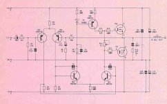
I did message an ex musical fidelity engineer who said they’re based on a hitachi design, others said Tim de Paravicini. To me they look very much like musical fidelity p170’s but instead of the dual mono the builder has separated into monoblocks.I think you will find the circuit is based on the original Hitachi application notes. Looking at your pictures and it all looks to fit...
The old Maplin amp was similar. I can see some differences in parts values but the basic structure looks the same.
View attachment 1112448View attachment 1112450View attachment 1112451
The design is good for 100w but the limitations come in the form of heat generation and heatsink size. Worst case dissipation in the amplifier occurs around 64% (from memory) of the maximum available output voltage.
They don’t even get Lukewarm to the touch , even when pushed .The design is good for 100w but the limitations come in the form of heat generation and heatsink size. Worst case dissipation in the amplifier occurs around 64% (from memory) of the maximum available output voltage.
- Home
- Amplifiers
- Solid State
- Is it possible to up the power of an amp ?


