Well the intended focus of this project, also includes expectations of technical excellence which is why everyone is up in arms about diffraction. Its not enough to sound realistic, we want it to be accurate. I am not so certain that any one measure is so out of whack that its actually impacting the performance of accuracy within what should be acceptable. Looking On-Axis there isn't any trouble until about 300hz. On Axis, Phase doesn't look a problem either. I need to Do the off axis measuring.

camplo. You can't use the word 'point source' to describe a speaker system. Point source is a theoretical construct which is a single entity, not a system.
You are corrupting the meaning simply by implying conditions. You are then inferring conclusions based on these conditions, while ignoring others.
A point source cannot itself be anything but perfect constant directivity. Can you say your speaker has that?
You are corrupting the meaning simply by implying conditions. You are then inferring conclusions based on these conditions, while ignoring others.
A point source cannot itself be anything but perfect constant directivity. Can you say your speaker has that?
flare
That's because I don't accept the premise that a true point source will image better than a "pseudo" one. To me this assumption is not valid. I know that there is no real data showing this to be true (except your subjective test of one subject, which I have to reject as patently biased.)This difference would be, once again, point source vs pseudo point source. The more of spectrum that emanate from a single point, the better.
Im pretty sure he has no interest in such a thing, but I do.
To me the shift in acoustic center at the crossover is far far less important than diffractions and reflections in the waveguide, neither of which have you attempted to control. So basically IMO you are hanging your hat on something which I discount and ignoring those aspects that I have found to be critical.
All I can say is, that outside of this aspect I am criticizing, the NS15 is the "perfect" or a iteration of a perfect, that can be practically achieved. I would like to hear them. My thoughts of late were that, if I had a NS15 at one meter, after being phase aligned to that position, I'd likely be sold....
Last edited:
It appears to me that you are consistently making tradeoffs towards ones that make little difference against others that are more critical. Like ever lower x-over points for 1/4 lambda at the crossover - bad tradeoff. You need a waveguide with minimum diffraction, etc. etc. You claim to be looking for perfection, but to me you are throwing the baby out with the bathwater.
Genelec, Danley's and most studio monitor designs share the philosophy of pursuing uniform pattern control over a wide portion of the audio spectrum, you certainly did not copy that.View attachment 1248143View attachment 1248144View attachment 1248146
Genelec and Tom Danely have the same exact philosophy in regards to bandwidth covered by the tweeter Axis. I just wanted to point out that I did not copy them... And that my design is an actual point source above 200hz..... Not a Pseudo Point Source 😎
Most monitor designs also share the philosophy of using drivers within their linear response region, which you don't.
Art
Hello Camplo
WRT diffraction this should help. At 200Hz?? I wouldn't worry. You would need a minimum 8'5" radius to accommodate the minimum
1/8 wavelength .
https://www.linkwitzlab.com/diffraction.htm
Rob 🙂
WRT diffraction this should help. At 200Hz?? I wouldn't worry. You would need a minimum 8'5" radius to accommodate the minimum
1/8 wavelength .
https://www.linkwitzlab.com/diffraction.htm
Rob 🙂
Last edited:
OK guys, teach a man to fish

Lets say this is my Vertical polar at 3m... halve all the angles I guess... First, I noticed there is no issues at 200hz.... We've got some stuff going on around 1k, all off axis. Can someone explain in layman's terms why this is the straw the broke the camels back.
Lets say this is my Vertical polar at 3m... halve all the angles I guess... First, I noticed there is no issues at 200hz.... We've got some stuff going on around 1k, all off axis. Can someone explain in layman's terms why this is the straw the broke the camels back.
Issue with diffraction is the back wave that emits towards direction where the sound came from. This is basically secondary sound source at the "edge" where diffraction happens. Whether this is audible depends on many things, like delay, bandwidth, direction, does it cause additional reflections and diffraction, and so on. All in all, when you see diffraction (or ripple in general) in a polar plot the take away is that it's not just direct sound that got measured but at least one another sound source making interference with the direct sound. In case of a horn, the diffraction related back wave emits back inside the horn basically, reflecting back again, diffracting again, and so on. Whether any of these are audible depends, but at least philosophically they are, single sound vs. multiple sounds, and the multiples not being exact copy of the direct and also smeared in time, although reduced in amplitude.
Even though you can EQ the on axis flat, as in the normalized plot you've posted, the on-axis sound consists of direct sound + n number of repeats of some bandwidth copy but with some delay (and opposite phase where if originated from diffraction).
That particular graphs looks peculiar, the "ridges" bend from high frequency to low frequency with increasing angle, which is not common sight so not quite sure yet what could be the source, perhaps due to rotation center used. Anyway, being a ripple they are very likely due to some secondary sound interfering with direct sound to a particular direction. These appear roughly between 700-5000Hz indicating that diffraction might be an issue as it appears to cover the whole midrange. If magnitude is low, perhaps it's not very audible.
What I think is most easily audible feature of diffraction is that it seems to contribute to sound changing constantly as you move in the room which is annoying if you are concentrating on the sound. While low diffraction (smooth DI) feels the same no matter movement. Well, I've got small sample set, old school monkey coffin speaker vs. low diffraction smooth DI speaker with waveguide.
Last edited:
Hi, if it is edge diffraction, you could just calculate where in time you should see it. Calculate path length on axis, from horn throat to your ear. Then calculate path length from throat, along with the horn profile, and from the mouth lip to your ear. If it's +40cm extra for the direct sound for example, then you should see some secondary sound around at 1.3ms mark or something like that.
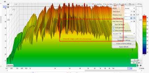
Your CSD plot slice interval seems to be 20ms, so the red area contains all reflections within about 6 meters from the moment of start. Can you drop the slice interval to 0.5ms or something, to fraction of size of your device (1ms is about a foot of sound travel)? I guess it would start showing something, if you drop the slice to some suitable length that really accentuates anything you'd like to inspect with it.
edit. Since the device is quite deep without much flare at the mouth, I speculate most of possible mouth diffraction related back wave goes back inside to the device and not towards listening window, and then comes out perhaps several ms later. So, experiement a bit and try to find if there is something special with some particular slice interval.
edit.
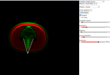
here is a crude horn in ripple tank to illustrate. The listener, upper edge of the screen, gets mostly direct sound as the back wave at mouth edge heads back where the wave came from, and is reduced from the direct sound at the moment. Then the parts that emitted at the edge keep on propagating to backwards direction, back to the device and to opposite side of the device, and chaotically afterwards to all kinds of directions after reflecting and diffracting again.
For example, consider what would be perceived right to the device, just the direct sound and some moments later back wave from the opposing edge arrives. This shows some issue with on axis as well, and what goes on axis depends on the angle "where the sound comes from".

https://www.falstad.com/ripple/Ripple.html?rol=$+3+512+64+0+0+768+0.048828125 s+2+182+329+2+0.46680807839388144+0+10.001413602849373+99.99941507823934+1+0 w+0+182+339+154+240 w+0+218+243+182+337
Your CSD plot slice interval seems to be 20ms, so the red area contains all reflections within about 6 meters from the moment of start. Can you drop the slice interval to 0.5ms or something, to fraction of size of your device (1ms is about a foot of sound travel)? I guess it would start showing something, if you drop the slice to some suitable length that really accentuates anything you'd like to inspect with it.
edit. Since the device is quite deep without much flare at the mouth, I speculate most of possible mouth diffraction related back wave goes back inside to the device and not towards listening window, and then comes out perhaps several ms later. So, experiement a bit and try to find if there is something special with some particular slice interval.
edit.
here is a crude horn in ripple tank to illustrate. The listener, upper edge of the screen, gets mostly direct sound as the back wave at mouth edge heads back where the wave came from, and is reduced from the direct sound at the moment. Then the parts that emitted at the edge keep on propagating to backwards direction, back to the device and to opposite side of the device, and chaotically afterwards to all kinds of directions after reflecting and diffracting again.
For example, consider what would be perceived right to the device, just the direct sound and some moments later back wave from the opposing edge arrives. This shows some issue with on axis as well, and what goes on axis depends on the angle "where the sound comes from".

https://www.falstad.com/ripple/Ripple.html?rol=$+3+512+64+0+0+768+0.048828125 s+2+182+329+2+0.46680807839388144+0+10.001413602849373+99.99941507823934+1+0 w+0+182+339+154+240 w+0+218+243+182+337
Last edited:
What is rise supposed to be set at and why? Maybe 1ms is wrong because 100ms is default. I think 1m is right...

Last edited:
Could you make the time range something like 4ms or so, as long that no room reflections hit it, but would include as much from the device itself, as possible.
I really have no clue how these graphs work 😀 I tried to make similar looking as yours with my measurement of a device to have a reference, but it's not looking similar having elevated "ridges" 😀
Anyway, with my data and settings I can get smooth ridges with small enough time range. This is in room measurement about 2m away, not sure if gating applies and how.

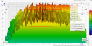
The ridges seem to get wavy with longer time range:

No idea why yours drops of and these don't, or what to interpret.
Anyway, with my data and settings I can get smooth ridges with small enough time range. This is in room measurement about 2m away, not sure if gating applies and how.

The ridges seem to get wavy with longer time range:

No idea why yours drops of and these don't, or what to interpret.
My measurement is outdoors, is that why>? Or is my source that much cleaner than yours?
Last edited:
Yours must be an indoor measurement. Heres one of mine at 1m indoors. I don;t have the uniformity of your decay, but I have way less decay period....what do we do with that?Anyway, with my data and settings I can get smooth ridges with small enough time range.
This makes me think of you and your strong criticism... So passionate yet why are you such a spectator this isn't that type of sport.You who have done so helped me make my own 2-Way monitor system
Share your measurements
"When someone consistently speaks negatively and criticizes others without being willing to share their own measurements or projects for scrutiny, it raises questions about their intentions and credibility. Engaging in constructive discussions should ideally involve an open exchange of ideas and a willingness to back up one's claims with evidence. Without such transparency, it becomes difficult to assess the validity of their criticisms or the foundation of their knowledge. It may be worth considering the credibility and value of their contributions in light of their unwillingness to share their own work."
I already know, you aren't going to share any measurements here. Shadow Warrior lol... Mr. I'm doing such a good job but I can't show anyone lol
OK yeah I believe you
If you are to share measurements they better be:
... or they are useless to the reader.
So room for massive improvements ;-)
//
- complete screenshots with axis scales AND legends
- marked with what is measured
- circumstances of each measurement (location, mic distance, smoothing, SPL, calibrated levels, x-over/PEQs,
... or they are useless to the reader.
So room for massive improvements ;-)
//
Any of that information is available but really half the battle is being present and willing to share, which I am, so nice try. You don't even practice what you preach. You are in the same boat as @paul7052 Talk it but don't walk it, and its annoying.
https://www.diyaudio.com/community/threads/hornflower-2-way-point-source.386363/post-7396365
In these instances We aren't really looking for FR as much as information from the Decay. The driver Voiced, and the Driver Raw are good starting points. You are right about making sure to include key information when sharing measurements, you are purposely incorrect in your delivery....
So room for massive maturing ;-)
Last edited:
- Home
- Loudspeakers
- Multi-Way
- Is it possible to cover the whole spectrum, high SPL, low distortion with a 2-way?