I am reading Self's book, he favor CFP over EF OPS. He claimed it's lower distortion. I am planning to do 3EF OPS, but I am considering a second version with EF-CFP (EF driving CFP). I want to know your opinions.
Also, what is the standard circuit added to prevent oscillation?
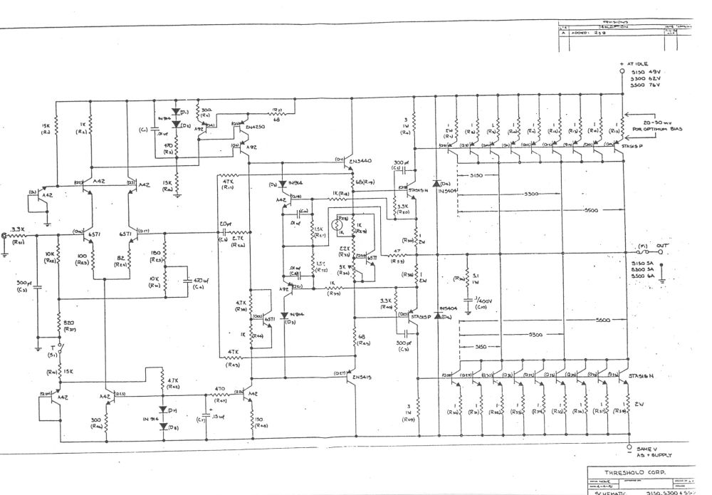
I also want to verify, CFP is perfect using NJL3281 and NJL1302 with build in compensating diode as you only need one transistor in EF configuration driving multiple common emitter transistors to provide the current. See attached image.
Also, what is the standard circuit added to prevent oscillation?
I also want to verify, CFP is perfect using NJL3281 and NJL1302 with build in compensating diode as you only need one transistor in EF configuration driving multiple common emitter transistors to provide the current. See attached image.
Attachments

Last edited:
Hi,
Lowest distortion at near full power is pretty meaningless,
and you can only get low THD+N figures near full power.
Self likes low numbers, simply because its commercial.
CFP is best in an almost meaningless context, numbers.
In the more subtle aspects of distortion spectrum versus
output level it sucks at low levels big time IMO compared
to EF, if you ascribe to 1st watt philosophy, EF totally wins.
Selfs comparisons suck bigtime. E.g. he slags off 50%
class AB as being worse than Class B, when it is clear
most of the time for typical usage it is miles better.*
rgds, sreten.
* A 50% Class AB amplifier run at <-6dB maximum
volume is a Class A amplifier, i.e. nearly all the time.
Last edited:
Even 3EF is prone to oscillate/ring. I will not consider EF driving CFP. You can simulate output stage with 1MHz square wave to see its response. Beside stability issues, CFP has lower bandwidth comparing to EF due to the existence of local feedback.
I have designed EF and CFP amplifiers and to be honest couldn't tell the difference.
A lot of distortion is got rid of by feedback in both topologies.
A lot of distortion is got rid of by feedback in both topologies.
I have simulated, built and listened CFP v. EF.
CFP has low distortion at high output, much less compressive distortion than EF. (odd orders)
However, setting the bias on a CFP is tricky, and you must be very careful to avoid thermal runaway.
EF is much easy to set bias and quite easy to thermal compensation with a Vbe multiplier. Using Self's EFII you maintain drivers on right through the cycle. This has advantages......
The listening experience of the EFII is best. The CFP is a bit hard at normal levels. The driver should be faster than the outputs; for this reason a 2SC4793 would be as a driver than a MJE1302. If the output can drive up to 40A, for example, and beta drops to say 30 at 10A each, the base current totals 1.33 plus 80mA quiescent, around 1.4A. A 2A driver with surge rating to 4A would be just fine, and a 2SC4793/MJE15030 would really be suited.
Hugh
Hi,
FWIW Self conjectures, take a simple EF, and CFP all devices.
Another option is just CFPing the output devices of a EF.
The latter appeals more to me, as its adding a pair of
small transistors to a CFP, to make bias the same as EF.
rgds, sreten.
FWIW Self conjectures, take a simple EF, and CFP all devices.
Another option is just CFPing the output devices of a EF.
The latter appeals more to me, as its adding a pair of
small transistors to a CFP, to make bias the same as EF.
rgds, sreten.
Hi guys,
That's the reason I post this instead of starting to design from reading the book. There is a lot of truth about people that write theory vs people in the trenches. I have seen the most respected Nelson Pass that is recognized as the tip top of high end amp designer. The Threshold schematic I saw are mostly Blameless type circuit that people laugh at or "improve upon"!!!! I for one don't crank the amp up all the way. I thing 10 good watts is much more important than full power.
From simulating the OPS, it really make me question why people debate about all the complementary IPS, push pull VAS and all!!! All the ones I simulated, the IPS/VAS combinations are at least 20 to 30dB lower in distortion than the OPS. What is the point of even talking about the IPS and VAS?
On top of the instability of the CFP, I found the bias adjustment is SO SENSITIVE also. You change the resistor divider a few ohms in the bias generator, you can move the current through the power transistor of the CFP from nA to hundreds of mA. this is not something I want to deal with.
I guess there is a lot of virtue of stop reading books and look at the reputable schematic like from Nelson Pass/Threshold. NOT ALL PEOPLE are stupid and psychosomatic enough to pay over $4000 for a Threshold amp. I listened to one Threshold in my friend's place, it's one of the best. There is a good reason that people can do, do. People that cannot do, teach/write........Sorry.
As a side question. I have been looking at 3EF this afternoon after I post this. I am looking at between 3NPN on one side and 3PNP on the other side vs, PNP and 2NPN on one side and NPN and 2PNP on the other side. Is there advantage of having PNP as one of the EF in the 3EF on the NPN side?
Last edited:
"I will not consider EF driving CFP"
Nelson Pass made many with that topology.
McIntosh made some excellent CFP driving EF outputs.
Nelson Pass made many with that topology.
McIntosh made some excellent CFP driving EF outputs.
Member
Joined 2009
Paid Member
I avoided CFP in the output stage for many years because some folk said it wasn't as good as EF. I tried CFP at the input and it was OK but harsh (I might be able to improve on that with the experience I have now). I tried it in the driver stage, CFP driving EF and I liked it. And then I tried it in the VAS stage and that sounded very clean.
A year ago, I thought that I should try CFP in the output for myself and hear it with my own ears. The result was an amplifier that sounds so good to my ears that I no further interest to design another solid state Class AB amplifier.
My point is not that CFP output is better than EF, but that you should try for yourself.
I've never experienced any dramas stabilizing a CFP output, and the sound quality is very good to my ears, in the proper circuit, properly biased.
The EF2 with cross-connected emitters also gives very good results, as does EF3, although this one is definitely a little tricky to stabilize.
The EF2 with cross-connected emitters also gives very good results, as does EF3, although this one is definitely a little tricky to stabilize.
How do you stabilize the CFP? Attached is the asc file and the FFT of the CFP output stage. I tried adding resistors, changing values of the resistors. I tried changing the miller cap and nothing help. You can see all the stuff above 1MHz. It's not even clean in simulation where there is no parasitic due to lead and trace.
Attachments
Add a B-C cap to the lower driver. Start with 33p and go up from there.
EDIT: I've opened up your file and realize you're trying to apply a CFP to a design with 4x pair outputs. I doubt you will be successful. One pair outputs, certainly, two pairs at a pinch.
Straight EF3 would be my suggestion here.
EDIT: I've opened up your file and realize you're trying to apply a CFP to a design with 4x pair outputs. I doubt you will be successful. One pair outputs, certainly, two pairs at a pinch.
Straight EF3 would be my suggestion here.
Last edited:
I am adding the cap across the C-B of all the transistor and running the simulation now.Add a B-C cap to the lower driver. Start with 33p and go up from there.
EDIT: I've opened up your file and realize you're trying to apply a CFP to a design with 4x pair outputs. I doubt you will be successful. One pair outputs, certainly, two pairs at a pinch.
Straight EF3 would be my suggestion here.
Yes, I was trying to use one transistor to drive 4 big output transistor in CFP. That has a big advantage of getting rid of one Vbe to compensate. Also, more importantly, the one driver transistor can be NJL type with compensation diode to get better thermal tracking. It would be very good if I can make it work. But if I cannot drive 4 pairs, then it's not worth the trouble. It's being able to use the NJL transistor that attracted my interest.
I was searching your posts from like two weeks ago about you use one PNP in the NPN side of the 3EF and one NPN in the PNP side. I could not find it. I have your schematic already, I just want to know more in how to design that. What do you call that? I want to find out more. I want to get more info to see whether I want to do that or not. I know it's some sort of diamond or whatever.
Last edited:
If memory serves, the sole reason that you parallel so many output devices at relatively low power levels is to maximise the Class A region while maintaining an optimum Oliver bias point.
A CFP output moves that bias point substantially lower so it is entirely counter-productive to these goals.
If I were you I would keep it simple and adopt a cross-connected EF2 as Hugh suggested or Locanthi EF3. If you like the idea of a really high Zout, but don't fancy the prospect of all those junctions influencing the tempco, then perhaps investigate the prospect of a simple cross-connected EF2 in conjunction with a VAS boostrapped by buffer (refer Figure 7.27b in APAD 6th Ed.).
I have built a couple of designs using BJT outputs and a diamond buffer driver stage in front of it, with the pre-drives working into bootstrapped current sources. Works beautifully. Refer Samual Groner's paper on Self for a description of the concept.
'zackly 😎
exactly !!!! 😀😀😀
This has been a joyful thread but since i am in a nice mood i will not start a battle over this thread ( even if some of the things written are completely wrong to my opinion )
fact 1
the only reason that EFP is more ""popular"" than CFP is because it will forgive mistakes designers make!!!
Fact 2
Any CFP circuit ( alike any EFP ) will be a walk in the park to stabilize as long as you know how to do it .In both cases you will loose something in order to preserve stability .How much is what makes the difference from amplifier A to amplifier B
In general designing or getting a personal amp is a question of proper targeting
Example :
I am in to soulful house music , strings, vocals, electronics , percussion , most of it uptempo from 120 to 128 BPM So i need speed , I listen to low listening levels so power is not an issue , i listen from near field monitors so sensitivity is an issue ( you need to be able to have a speaker that "talks" enough in low power ) again power ( of the speaker is not an issue ) Low listening levels needs except speed loads of bandwidth cause if not especially in low power there is no ends like high and low ...
See what i mean ?
To be able to do that before you make the amplifier you need to have the experience to actually predict the sound of the amp based on the topology divided from stage to stage ....Actually very few people can do that ...
In PA7 Nelson did his thing with the bias like putting inside the amp a trick or a treasure or a treat for the feature repair man to puzzle with ....Nice ha ?
Member
Joined 2009
Paid Member
one option is to have each one be a CFP pair, a compound device, put them in parallel after you make them CFPs.
- Status
- Not open for further replies.
- Home
- Amplifiers
- Solid State
- Is CFP better than EF?