But that defeats the most attractive point!!! With one transistor driver, you can use the NJL with bias diode to track the temperature.one option is to have each one be a CFP pair, a compound device, put them in parallel after you make them CFPs.
I am playing with different values of resistors, seems like higher emitter resistor of the driver tame the high frequency stuff better. I am still reading Self's book as he is more into the CFP. Also doing the simulation.
I would go for EF's. Just have a look at D.Self in his Audio Power Amplifier Design Handbook (6th ed) to see why EF's are smoother at low outputs than CFP's: On Page 277/278 the Figs. 10.30 and 10.31 seem to make clear that an optimally biased EF has a better linearity around V_IN=0V. And also, why it is preferable to choose a small Re: Low Re's do further improve the output linearity. So I would prefer EF's with Re's=0.1R for a standard design. However, CFP's seem mandatory within Self's class XD-approach: It might be simply impossible to tame the Vbias in a very asymmetrically heated, XD-class EF setup. The temperature difference and behavior of the upper and the lower power output device will be too difficult to control. Therefore, CFP's are a must, because you will only have to assess the drivers temperature for a correct Vbias.
I am still reading D Self's book and do simulations. So far, I found shortcoming of CFP from Self. Self claimed the crossover distortion gets worst when you parallel CFP pairs where 3EF gets better when you parallel more pairs. That's very important. CFP is for lower power amp only better for lower bias. But if you want more power, 3EF seems to win out.
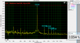
I have been doing simulation, I have not completed it yet, I will post the result when I complete them. So far, when I compare 4 stages CFP vs 5 stages 3EF, it's close. I can say for sure from simulation with 7Vpeak output, 3EF with 200mA per pair driving 4ohm resistor to keep in class A, distortion is at least 9dB better. 2nd and 3rd H is -105 and -110dBV, so the signal to distortion ratio is over 120dB!!!!
I am still running 1KHz 30Vpeak, going to run 20KHz 7Vpeak and 30Vpeak. It's going to take 2 hours to run each.
Alan0354
To CFP or not to CFP ? --> That is the question 😀
Prapobly there is no simple answer to that question. In my opinion -100dB or -110dB harmonics level is not making any diffrence. IMHO the harmonics ratio is a bit more important.
Recently I have done my first CFP amp (input,VAS and output stage) and must say that it sounds owesome even in unfinished state.
I didn't noticed any harsness at low volume levels also. I didn't noticed any crossover issues with sine and triangle wave forms either (on the scope readings).
I still have some problems with oscillations so I had to put 100pF caps at the CFP drivers to get rid of them (I do not know if this is good practice ?).
The conlusion is that it is definetley worth of trying to put CFP output stage and do some listening tests.
I do not ''hear'' any disadvantages of CFP anyway.
Regards Peter
Attachments
I finished 4 FFT for each
1) 3EF with 5 stages, 200mA per stage(pair) of total 1A quiescent current.
2) 4 Stages CFP with 200mA per stage.
I simulated 1KHz in 7Vpeak output and 30V peak output. FFT setting is 50mS run time ( 50cycles) and 0.005uS step.
I simulated 20KHz in 7Vpeak output and 30Vpeak output. FFT setting is 5mS run time (50cycles) and 0.0005uS step.
Attached is the asc file and the result.
The distortion is slightly lower if I use 0.12ohm emitter resistor for the power transistors, but I feel more comfortable with 0.33ohm for real life mismatch and current sharing.
From simulation, it is proven it is VERY important for the 3EF to satisfy Oliver's optimization using emitter resistor that drop 26mV with the bias current.
Attachments
-
3EF 5stages 20KHz 1.5Vin 5mS 0.0005uS 200mA Olivers.pdf83.9 KB · Views: 107
-
CFP 20KHz 1.5Vin 5mS 0.0005uS 1 7.5 0.33ohm 200mA.pdf87.3 KB · Views: 117
-
3EF 5stages 1KHz 1.5Vin 50mS 0.005uS 200mA Olivers.pdf113.6 KB · Views: 82
-
CFP 1KHz 1.5Vin 50mS 0.005uS 1 7.5 0.33ohm 200mA.pdf114.7 KB · Views: 83
-
3EF 5stages 20KHz 0.35Vin 5mS 0.005uS 200mA Olivers.pdf105.6 KB · Views: 110
-
CFP 20KHz 0.35Vin 5mS 0.005uS 1 7.5 0.33ohm 200mA.pdf103.6 KB · Views: 71
-
3EF 5stages 1KHz 0.35Vin 50mS 0.005uS 200mA Olivers.pdf97.6 KB · Views: 88
-
CFP 1KHz 0.35Vin 50mS 0.005uS 1 7.5 0.33ohm 200mA.pdf97.6 KB · Views: 151
-
Complete amp.asc22.9 KB · Views: 110
Last edited:
I just finished another set of FFT. This time is the exact same circuit but bias adjusted to 100mA per stage instead 200mA. My observation is the distortion is very similar at 1.5V input (30Vpeak output). But 3EF is much more superior with 200mA bias for 0.35Vpeak input (7Vpeak output) as it's working totally in Class A. I think 7Vpeak cover most of the regular listening level.
To my surprise, even the CFP performs better at 7Vpeak output with 200mA than 100mA. But still not coming close to 3EF 200mA at 7Vpeak output.
I think I feel good in my decision of running hot at 200mA per stage for 5 stages 3EF. I am running at +/-40V rail to keep the dissipation down to 160W of heat to get about 8W of Class A. I believe 8W is plenty for reasonable listening level.
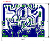
I did optimized the CFP before doing the simulation. If anyone have suggestion to improve the CFP from my schematic, I am all ears. I am having the OPS as separate board, it only cost me $106 for a run of 10 for 2mm thickness. If I am willing to go down to 1.6mm, it's only $67 for 10.
To my surprise, even the CFP performs better at 7Vpeak output with 200mA than 100mA. But still not coming close to 3EF 200mA at 7Vpeak output.
I think I feel good in my decision of running hot at 200mA per stage for 5 stages 3EF. I am running at +/-40V rail to keep the dissipation down to 160W of heat to get about 8W of Class A. I believe 8W is plenty for reasonable listening level.
I did optimized the CFP before doing the simulation. If anyone have suggestion to improve the CFP from my schematic, I am all ears. I am having the OPS as separate board, it only cost me $106 for a run of 10 for 2mm thickness. If I am willing to go down to 1.6mm, it's only $67 for 10.
Attachments
-
3EF 5stages 20KHz 1.5Vin 5mS 0.0005uS 100mA Olivers.pdf88.3 KB · Views: 72
-
CFP 4stages 20KHz 0.35Vin 5mS 0.005uS 1 7.5 0.33ohm 100mA.pdf81.7 KB · Views: 58
-
3EF 5stages 20KHz 0.35Vin 5mS 0.005uS 100mA Olivers.pdf80.9 KB · Views: 81
-
CFP 4stages 1KHz 1.5Vin 50mS 0.005uS 1 7.5 0.33ohm 100mA.pdf113.9 KB · Views: 57
-
3EF 5stages 1KHz 1.5Vin 50mS 0.005uS 100mA Olivers.pdf113.2 KB · Views: 90
-
CFP 4stages 1KHz 0.35Vin 50mS 0.005uS 1 7.5 0.33ohm 100mA.pdf104.9 KB · Views: 58
-
3EF 5stages 1KHz 0.35Vin 50mS 0.005uS 100mA Olivers.pdf104.2 KB · Views: 70
-
CFP 4stages 20KHz 1.5Vin 5mS 0.0005uS 1 7.5 0.33ohm 100mA.pdf88.9 KB · Views: 70
Last edited:
Can you post the schematic?My Tiger 0.01 had the lowest measurable IM distortion (actual amp) at 50mA idle current.
Another example of a rather "cold" design.
Dual-CFP output stage - separate drivers for each output pair.
Minimal distortion (both THD and IM) - at 30-35mA per pair (live measurements).
Thermal sensor (Vbe multiplier) tracks the drivers only (separate heatsink).
>CFA-CFPx2 high-performance amplifier<
Dual-CFP output stage - separate drivers for each output pair.
Minimal distortion (both THD and IM) - at 30-35mA per pair (live measurements).
Thermal sensor (Vbe multiplier) tracks the drivers only (separate heatsink).
>CFA-CFPx2 high-performance amplifier<
"Can you post the schematic? "
http://www.swtpc.com/mholley/RadioElectronics/Mar1973/RE_Mar_1973_pg42.jpg
http://www.swtpc.com/mholley/RadioElectronics/Mar1973/RE_Mar_1973_pg42.jpg
Djk, thanks for sharing. This is a cool one - not just CFP, this is an OPS with gain. Well designed and properly compensated.
Comment in general - such structures are low distortion, but "dangerous creatures", subject to violent, difficult-to-tame oscillations, if not designed AND BUILT carefully enough.
This is the same as with many other high-performance things - you either do it right and get rewarded by top performance, or it's a total disaster 😉
"this is an OPS with gain"
Many people had a problem building these, the instructions were non-existant. Mine oscillated at about 2Mhz because of the input coupling capacitor, it was a tantalum type.
I designed an amplifier around a 5532 driving this kind of output stage (3x voltage gain) in 1997 and people were stunned with the sound quality, even though it ran class B, zero bias current in the output stage.
Hi DJK
Thanks for the schematic.
I have been reading chapter 10 of Self's book, I find it quite confusing. I think there is typo on the Fig. number. Also, he jump back and fore between talking about EF and CFP stage without really telling the reader. Worst is on page 279.
Self never explain why you can run much lower quiescent current with CFP. Also, he kept talking about Class B is better than Class AB, BUT in page 278, he listed the optimal quiescent current to get the Vq. For EF he even suggested using 0.1 ohm RE and run 213mA current!!!! That is what I am doing and that is as far from Class B as can be!!! I don't even know what he meant about class B!!!
I read Chapt 9 and 10, he never explain CFP, how it works, how RE affect the crossover distortion. He just GAVE the optimal point. I think Cordell's book is so much better, Cordell just did not get into CFP as much. I got spoiled by Cordell.
Do you have explanation why CFP can run much lower quiescent current?
Last edited:
Anyone have a good article explaining CFP, how to set the emitter, collector resistor of the driver, how to set the emitter resistor for the CE power transistor. And more important, how to avoid oscillation? I read Cpt 9 and 10 of Self's book, he sure did not explain any of that.
Self claimed the crossover width of CFP is a lot narrower than EF. Width is only 1V max compare to 18V of EF. He said narrower width generates high harmonics that cannot be reduced by GNFB. Isn't that bad? Isn't that means CFP has worst crossover problem? AND that this is worst as crossover distortion affect greatly at low volume.
Self claimed the crossover width of CFP is a lot narrower than EF. Width is only 1V max compare to 18V of EF. He said narrower width generates high harmonics that cannot be reduced by GNFB. Isn't that bad? Isn't that means CFP has worst crossover problem? AND that this is worst as crossover distortion affect greatly at low volume.
Last edited:
Alan 0354...I have a question :
Can you use in the near feature the results of your work ? Meaning that have you already established a frame that says that: "i need an amp that has this type of harmonics , bias , distortion, why not oscillation versus the other amp that has the opposite or less or more ? "
Cause if you don't there is no point on continuing doing that since eventually you will become a simulator expert not an amplifier expert .
I could suggest that you should make a typical EFP amplifier with 35+35 rails listen to it for a period of time then make a P3A also listen to it for a period of time and you will learn a few things that simulator cannot tell you .
Regards
Sakis
Hi East Electronics
I have every intention in building the amp and will be within two months. I already bought the most expensive parts, the heat sink chassis and the 625VA 40-40 transformer. I layout one version of the OPS and I plan on sending out a CFP version. I plan on fabbing 3 version of the IPS/VAS boards one Blameless, one complementary IPS and maybe one different one that I have not decided yet.
Things will move faster shortly, I just ordered 1/3 of the components that cost me $200 last night. So I am already close to $600 out of pocket already. My style of engineering is to try to know as much of the ins and outs before I commit, I expect the successful ratio will be very high.
Understanding the way the CFP operates is not an easy thing even though described by many as a quite simple principal
you may go as you please i only suggested that you start small to begin with
Kind regards
Sakis
you may go as you please i only suggested that you start small to begin with
Kind regards
Sakis
I can take my time as I have the 3EF OPS that is a lot closer. I am investigating the option of using an opposite BJT in the 3EF and I can finalize the pcb to sent out. At least I can get one version going. From the simulation, 3EF actually have an edge at 8W output over CFP. I can do the CFP as a backup. I just want to leave no stone unturned.Understanding the way the CFP operates is not an easy thing even though described by many as a quite simple principal
you may go as you please i only suggested that you start small to begin with
Kind regards
Sakis
From my simulation, I can get the 4 stages CFP having just as low distortion at full power as the best 3EF I have. But the resistor values are much lower than in the book. I simulated the circuit is Threshold and I improved upon it with slightly different value resistors. I get the best result running at 200mA per stage.....against Self's claim to run at low current. There seems to be a sweet spot there that I want to understand. Learning is part of the fun in building the amp, I am not going to be happy just to build a good sounding amp, I want to know why.
Also, I have to space the spending out a little so I don't alarm my big boss....the CFO..... too much. I bought the PT first, then I bought the chassis two weeks ago, I just ordered $200 worth of parts. I am going to wait about two weeks before ordering the rest!!!! You know how that works, the big boss will give you instant performance review, don't have to wait till the end of the year!!!
Last edited:
- Status
- Not open for further replies.
- Home
- Amplifiers
- Solid State
- Is CFP better than EF?