Don't bother. Just use multiple capacitors in parrallel. Like if you think you need 10,000uf use 4 2,500uf. But honestly people usually use to little, so use more! I think TNT had a guide to the amount, and it's substantially higher that most people use. I recommend more as well, but not with just a couple big caps; more smaller ones!
By doing that you won't get ringing, you'll lower impedence, and you'll increase quick current capabilities by not going too big. Plus it doesn't cost a lot.
By doing that you won't get ringing, you'll lower impedence, and you'll increase quick current capabilities by not going too big. Plus it doesn't cost a lot.
And performance is better, fast charge/discharge, better linearity.Don't bother. Just use multiple capacitors in parrallel. Like if you think you need 10,000uf use 4 2,500uf. But honestly people usually use to little, so use more! I think TNT had a guide to the amount, and it's substantially higher that most people use. I recommend more as well, but not with just a couple big caps; more smaller ones!
By doing that you won't get ringing, you'll lower impedence, and you'll increase quick current capabilities by not going too big. Plus it doesn't cost a lot.
For a 22,000uF a set of three 8,200uF should do job.
There is nothing more useless and ridiculous than all those remote capacitor boards (with all sorts of bypasses) traditionally used in class AB amplifiers. This can only come from people having zero understanding about high frequency electronics. Every 3 cm of wiring (approx 15nH) is as inductive as a big electrolytic capacitor.
My first naïve attempt at class d was on my test bed which has 2 off 10,000uf but on 6 inch flying leads with croc clips on the end. The class d amp just wouldn't run without going into protect mode.
I then added the 10,000uf on the pc band the amp worked great right into hard clipping.
I sold one of my amps and the buyer rang up and told the amp was crap and kept going into protect. I asked if he had altered anything and he said he had just put the output transistors on 4 inch flying leads to a heatsink off pcb.
Off course putting them back on the pcb fixed his problems.
A lot of people think class d is like class ab and its much higher frequencies.
Don't bother. Just use multiple capacitors in parrallel. Like if you think you need 10,000uf use 4 2,500uf. But honestly people usually use to little, so use more! I think TNT had a guide to the amount, and it's substantially higher that most people use. I recommend more as well, but not with just a couple big caps; more smaller ones!
By doing that you won't get ringing, you'll lower impedence, and you'll increase quick current capabilities by not going too big. Plus it doesn't cost a lot.
And performance is better, fast charge/discharge, better linearity.
For a 22,000uF a set of three 8,200uF should do job.
The "many small caps are superior to less big ones rule" is as old as it is wrong or
at least way too general.
Going for one big but higher quality 22 mF cap is more effective than 10 standard
quality 2.200 µF ones at the same cost. Just read datasheets and compare ESR.
One small 1000 µF lytic + one 1 µF poly or similar will help further, but they need
to be placed fairly close to the load.
This sums up the gotchas of paralleling caps, I guess.
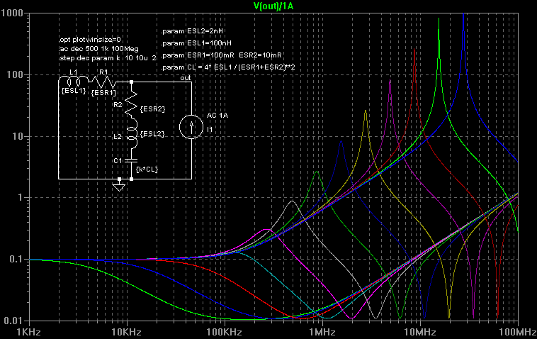
Every time 2 caps are paralleled, a RLC network is created.
If it is not well damped, you get the spiky impedance curves shown above. The impedance will be high at some frequency, making your decoupling useless, and noise filtering will be weak.
With the right capacitor combination, it is even possible to greatly amplify power supply noise. All it takes is that some noise frequency (from rectifiers, or a nearby digital chip, etc) happens to meet the resonance peak, and boom.
When someone talks about how adding or replacing capacitors changes the sound of a device, this is the first explanation to examine.... especially if said "tweak" involves low-ESL/ESR caps connected with very high inductance... Given the tendency of opamps to act as RF detectors, putting tuned LC resonators in the power supply is a sure recipe to "tweak" the sound...
All those RLC networks should be properly damped for correct operation. Not enough damping and it will ring. Too much damping and transient response / impedance won't be as good as they could be.
This resistance is usually the cap's own ESR, one can also add some low value resistors, but this increases inductance, which needs more resistance to damp...
If you run some simulations or a test with a network analyzer, it quickly becomes obvious that modern polymer caps like Oscons, SPCaps, R5, etc, etc, have such low ESR that the amount of inductance needed to make a nice high-Q tuned LC with them and a ceramic cap in parallel is really, really low.
Actually, the only way to parallel these caps and some ceramics is to use close power and ground planes, and even that takes some care. Power traces don't work. Their inductance needs higher ESR caps for proper damping, so another capacitor type should be selected, or some ferrites, or RC snubbers added. Leaded film bypass caps don't work either, too much inductance, unless the bypassed capacitor is a high-ESR one.
Basically, only two ways work :
- The oldskool way, large bulk cap with high ESR, bypassed by film cap, here the large ESR damps the resonance.
- The newskool way, power and ground plane, low-ESR polymers, and SMD ceramics properly mounted. Local power planes can be small (like a small copper pour) as long as they are connected to other power capacitors which something that damps the LC, like a ferrite or a resistor, not a simple track.
Mixing the two is asking for trouble. Any trace used to parallel caps which doesn't have a ferrite in it is trouble. Any capacitor that isn't a properly mounted (ie, tight vias, no traces, etc) SMD chip is an inductor. Especially, leaded film caps are inductors since their HF performance is much much worse than a modern polymer cap....
Here, the long leads mean the OSCON is not only useless, but will actually degrade performance :
Another example, much worse (see second picture). Here, the film cap and lead iductance form a LC resonator with the large cap. But the worst is the wires, which will add a lot of L, which is kinda sucks, since at the other end of the cable, there are ... more capacitors, of course. Not to mention the fact that the wire's impedance will turn rectifier current pulses into nice voltage pulses... arg.
Attachments
Last edited:
You mean just behind the speaker connectors?The "many small caps are superior to less big ones rule" is as old as it is wrong or
at least way too general.
Going for one big but higher quality 22 mF cap is more effective than 10 standard quality 2.200 µF ones at the same cost. Just read datasheets and compare ESR.
One small 1000 µF lytic + one 1 µF poly or similar will help further, but they need to be placed fairly close to the load.
You mean just behind the speaker connectors?
No. The power supply's load. i.e. The output-stage's active high-power devices.
The "many small caps are superior to less big ones rule" is as old as it is wrong or
at least way too general.
Going for one big but higher quality 22 mF cap is more effective than 10 standard
quality 2.200 µF ones at the same cost. Just read datasheets and compare ESR.
One small 1000 µF lytic + one 1 µF poly or similar will help further, but they need
to be placed fairly close to the load.
Really?! In every case I have ever looked at, almost every parameter was able to be better when using multiple smaller caps in parallel. It can almost always be cheaper than one large equivalent-value cap, and sometimes much cheaper. And with proper physical implementation it can always give much lower ESR and ESL. It also greatly improves the reliability and the robustness (in terms of insensitivity to a single out-of-spec or failed-open cap). And in linear power supplies, using multiple smaller parallel caps can make it much easier (and cheaper) to meet the specs for the maximum peak and maximum average ripple currents, by dividing the current between multiple caps, and at the same time can enable extending the caps' lifespans due to less i-squared-ESR heating of each cap and better overall cooling due to increased total cap surface area.
No. The power supply's load. i.e. The output-stage's active high-power devices.
Like these red electrolytics just aside the big ones?
An externally hosted image should be here but it was not working when we last tested it.
Really?! In every case I have ever looked at, almost every parameter was able to be better when using multiple smaller caps in parallel. It can almost always be cheaper than one large equivalent-value cap, and sometimes much cheaper. And with proper physical implementation it can always give much lower ESR and ESL. It also greatly improves the reliability and the robustness (in terms of insensitivity to a single out-of-spec or failed-open cap). And in linear power supplies, using multiple smaller parallel caps can make it much easier (and cheaper) to meet the specs for the maximum peak and maximum average ripple currents, by dividing the current between multiple caps, and at the same time can enable extending the caps' lifespans due to less i-squared-ESR heating of each cap and better overall cooling due to increased total cap surface area.
I always thought like that, specially in terms of cutting cost. A brand new Nichicon 22,000uF 80V KG series Super Through cost like a Ferrari...

ticktock why on earth would you compare a high quality capacitor (one large) to several small non-quality capacitors. I use good capacitors period, and parralelleling is wonderful. The non-believers use network analyzers while the rest of us enjoy greatly improved music.
peufeu I don't understand why your analizer program shows something entirely different than just capacitors. Ringing occurs in mucher lower capacitance ranges than I'd use, in any frequency I'd be concerned with. I also don't use bypass caps, ever. I don't use capacitors for power in a network. I don't use snubbers. Where ever the resonate peak is at, it never hits. The holes in some of what you are saying aren't worth exploring too much. Your engineering brain can tell you whatever it wants, people still do things in amplifiers that probably cost more than you make in a year, and most importantly no one's ears care about text on a forum.
gootee you must care about how your stuff sounds! Indeed ESL and ESR drops a lot. But frankly there is a question not being well addressed, minor (potential) issues with inductance vs. proper power delivery and which is a greater improvement to sound. I know what my ears like...
Like these red electrolytics just aside the big ones?
An externally hosted image should be here but it was not working when we last tested it.
The smaller capacitors have their own Graetz bridge and they're not parallel to the big ones.
To me Peufeu's comment is strictly right. This is an area where DIYers don't come as it is a dark and lonely place and most that dare to go there don't know the way. I wish I would have more knowledge on that subject. Working on it though 😉
Paralleling recent large aluminium electrolytic caps brings no improvement. Better use one large one. Caps have changed and their ESR is very very low now. The polymer caps have extreme low ESR. I still make the mistake paralleling all electrolytic caps with a 100 nF ceramic cap but it is in fact a bad (old) habit when using modern electrolytic caps. However when there are tens of millimeters between the electrolytic cap and the ceramic bypass caps straight at the pins of an IC I do see improvement. Might be luck...
In fact using just polymer electrolytic caps (and no bypass caps) is the way too go but I remark that it is very hard to get rid of old bad habits. The thought that the electrolytic cap will dry out and become higher ESR comes to mind.
Last edited:
I imagine it is because his program correctly includes the stray inductance of the capacitors. If it were not for finite ESR too the peaks would be infinite! If you are going to 'bypass' a cap then make sure the cap has poor (i.e. highish) ESR, or use the wiring to add some losses.Destroyer OS. said:peufeu I don't understand why your analizer program shows something entirely different than just capacitors.
Raising doubts about someone's earning ability because you appear not to understand what he says is not a helpful way to conduct a technical debate.Your engineering brain can tell you whatever it wants, people still do things in amplifiers that probably cost more than you make in a year, and most importantly no one's ears care about text on a forum.
I learned a lot about decoupling in class d amps I designed.
The IC's need to be closely decoupled with 100nf.
The output mosfets needs C and CR to damp switching spikes.
The power supply had 2 off 10,000uf but I also added 47uf across these to damp higher frequencies.
The IC's need to be closely decoupled with 100nf.
The output mosfets needs C and CR to damp switching spikes.
The power supply had 2 off 10,000uf but I also added 47uf across these to damp higher frequencies.
I imagine it is because his program correctly includes the stray inductance of the capacitors. If it were not for finite ESR too the peaks would be infinite! If you are going to 'bypass' a cap then make sure the cap has poor (i.e. highish) ESR, or use the wiring to add some losses.
Raising doubts about someone's earning ability because you appear not to understand what he says is not a helpful way to conduct a technical debate.
To me the money thing is a stupid and disdainful remark and I over-read it till DF96 replied. Especially the "people still do things in amplifiers that probably cost more than you make in a year" is a painfully clear example of the "I do because I can" mentality from a certain area.
Maybe you know but we try to make a nice DAC and that same mentality strikes me over and over again when people do plain stupid thing like connecting the device to an AC power supply "because they can". Then I have to solve their problems because the device is not working as advertised and all that legal BS in which they seem experts.
"I do because I can"/"I do because I want"/"I do because I have the money" are not ways of discussing a technical matter, it just are ways of evading knowledge in an appalling display of stupidity. Although I am not the one that made the remark I feel ashamed. Keep on the good work Peufeu !
Last edited:
ticktock why on earth would you compare a high quality capacitor (one large) to several small non-quality capacitors.
What is the "quality" of a capacitor ? Low ESR/ESL ? Nonlinearity (dC/dV) ? Price ? Gold plating ? Other stuff ?
peufeu I don't understand why your analizer program shows something entirely different than just capacitors.
Sorry, I don't get what you mean here. Network analyzer is not a program, it is a device you put on the bench like a scope. It measures impedance/transfer function wrt frequency of any stuff you plug into it. It can be used to analyze the impedance of a power supply, caps, regulators...
Your engineering brain can tell you whatever it wants
When I listen to music, honestly, I switch off the engineering brain. Who gives a **** ?
Hey, you just gave me an idea. I wanted to put an ABX into the next amp that I'll build "someday"... to test stuff... what if on startup, it would randomly choose between switching in one of two amps in the same box... that would be fun, not knowing which circuit is actually running, therefore, no prejudice ! Just like blind dates, but naked and in the dark. Hm.
Paralleling recent large aluminium electrolytic caps brings no improvement. Better use one large one. Caps have changed and their ESR is very very low now. The polymer caps have extreme low ESR. I still make the mistake paralleling all electrolytic caps with a 100 nF ceramic cap but it is in fact a bad (old) habit when using modern electrolytic caps
Well you have to look at inductance of the cap itself, the way it is mounted on the PCB, and the inductance of traces. Look at the frequency responses of ceramic, oscons, etc, in manufacturers docs and calculate ESR/ESL, it is not very complicated... a $0.50 Alu-polymer cap, 6-8mm diameter, has a few nH inductance, ie, replace the capacitor with a wire soldered to the same PCB holes, not much difference WRT inductance, pretty amazing IMHO...
I've got a pcb with a few DC-DC converters on it. There is a Panasonic FC cap on the output of one converter, a nichicon R5 cap on another DC-DC, these caps are like half my pinkie finger nail, eat 1-2 amps ripple at 250 kHz, losses are ludicrous, and the output is smooth as a baby's butt. These caps deserve some respect...
If you use traces and not a close coupled power/ground plane, basically, the truth is, all this doesn't matter, a few mm traces is enough to make more inductance than the cap's own ESL... OSCON or R5/R7 or whatever, when not connected to coupled planes, or directly at the target chip's pins, it is worse than wasted...
The money comparrison was meant to be saying that people purchase things that are considered inferior from a perspecive of engineering, for price ranges that go beyond that of almost anyone. Frankly I think many products out there are already world class, when they are powered well, even though they cost very little.
Cap quality is somewhat subjective, but for power supply low ESL/ESR is desired, and there are numerous reputable capacitor lines.
I see something on my computer screen, it sure looks like a program to me. I can't be responsible for knowing whether it is directly connected to a computer or not for recieving the visual representation of the analization. Seriously.
Smaller caps respond differently. However, this all depends on differences in design between some things. Constant current vs smps, etc. Generally I'd just say most people use too little when it comes to a lot of contemporary gear.
Personally I'm a big fan of the new small SMD stuff that is used in non-signal. I'm not stuck on through hole, but I'll tell ya, I prefer to work on it 😉
Non-believers in what?The non-believers use network analyzers while the rest of us enjoy greatly improved music.
And shouldn't you be saying the believers in physics. Who do tend to look at an amp that cost more than they earn in a year with some suspicion.
Funny all the documentation I have on decoupling/bypass caps seems to think they are important, I wonder why?
Originally Posted by Destroyer OS.
Your engineering brain can tell you whatever it wants
same, even your non-engineering brain can tell whatever it wants...it is called free will...
From first page:
Does all this apply to wiring from out-of-the-board big capacitors as well? For example, in vintage amps often we have the big caps connected with a lot of long wires to the main board...
Below the Yamaha A-700 which works both class A and class AB
...
The root of the problem is exactly the fault that we are trying to solve: Inductance. The series inductance of any capacitor (not just electrolytics) will resonate with whatever other capacitor you put in parallel. You can assume 1nH per mm of pin spacing. A large-can electrolytic with 10mm pin spacing soldered to a PCB usually exhibits 10nH to 15nH. A film capacitor with 15mm terminal spacing exhibits approx 15nH too. Bigger films with 40mm or 50mm spacing exhibit approx 50nH (they are completely useless for bypassing). SMD chips may exhibit 2nH or so.
(...)
Finally, note that I'm assuming that all the capacitors are mounted very close together in a double sided PCB with ground and power planes, with the load (be a class-AB amp, a class-D amp or a SMPS) sharing the same PCB and very close to the capacitors so that path inductances become negligible.
Even just 2 cm of wiring or conventional PCB tracks (with no ground or power planes) will add enough series inductance (5nH per 1 cm) to render any "remote" bypassing USELESS!!
There is nothing more useless and ridiculous than all those remote capacitor boards (with all sorts of bypasses) traditionally used in class AB amplifiers. This can only come from people having zero understanding about high frequency electronics. Every 3 cm of wiring (approx 15nH) is as inductive as a big electrolytic capacitor.
Does all this apply to wiring from out-of-the-board big capacitors as well? For example, in vintage amps often we have the big caps connected with a lot of long wires to the main board...
Below the Yamaha A-700 which works both class A and class AB
An externally hosted image should be here but it was not working when we last tested it.
An externally hosted image should be here but it was not working when we last tested it.
- Status
- Not open for further replies.
- Home
- Amplifiers
- Power Supplies
- Is bypassing PSU capacitors effective?