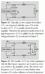
Just a silly question from a newbie.
The scenario
Let us consider a linear power supply with a 100uF electrolytic capacitor at the output. The capacitor becomes inductive at high frequencies so the PSU impedance rises. To flatten the power supply impedance a film capacitor (e.g. 0.01uF to 0.1uF) is used to bypass the electrolytic capacitor.
My hypothesis
When there is a sudden current demand from the circuit, the voltage drops at the output of the regulator. PSU capacitors are reservoir capacitors so when the voltage drops at the output of the regulator, the capacitors that are fully charged will then supply the current, before the regulator recovers.
For the 100uF electrolytic capacitor, due to the larger capacitance it can supply the current without much voltage drop. It is like a large battery. However, for the film capacitor of 0.01uF, the capacitance is so small and it is just like a tiny battery that runs out immediately. When the circuit draws current at high frequencies, due to the lower impedance of the film capacitor it always gets used before the electrolytic capacitors, and its "battery" life is quickly run out before the regulator recovers. So the current must be drawn from the electrolytic capacitors that have higher impedance at higher frequencies.
In other words, if the above hypothesis is correct, film capacitor bypassing would be fairly ineffective.
Is this right? Please excuse me for asking such a simple question.
Regards,
Bill
As far as I can tell,that's standard practice,For some of the reasons you mention,and more.
Another reason I can think of is for bypassing RF/HF noise.
Another reason I can think of is for bypassing RF/HF noise.
Forget all this pseudo-scientific analysis, it's all wrong. Time is continuous and all possible delays come from transmission line effects only, which you may consider negligible for very short distances. Output current will come from *all* components at *all* times, it's only the ratio what changes depending on time and stimulus.
You have to learn to model everything as R, L and C elements and check impedance in the frequency domain. Results may seem a bit counter intuitive at first, but it's the only way to predict exact circuit behaviour.
For example, a small film capacitor in parallel with an electrolytic capacitor not having high ESR will actually result in higher overall output impedance, ringing and very bad performance in the low Mhz range.
The other way to learn about the subject is to build a current pulse generator with very fast rise and fall times and use it to see the actual pulse behaviour for whatever circuit configuration you want on the oscilloscope. I use to check my class D and SMPS designs that way.
Is bypassing PSU capacitors effective?
A sily like question to Experts but very useful to Newbie.
Hi HiFiNutNut,
Let us forget all pseudo-scientific analysis and move logically.
The scenario- What is the meaning of Bypass? It is the route that is used to avoid the main route. Here, the definition is perfect. This film capacitors act as an alternative route for the high freq. spikes/RF/HF signals in the circuit if any, known as noise which can not be handled by Bigger Electrolytic Capacitors. These film capacitors are made in such a way that they are having low impedance for RF/HF freq. and so, by handling those, keep the main circuit safe for lower freq. and linear power supply is meant for that.
Analysis -- Your 100 uf Electrolytic capacitor only will act as main reservoir capacitors as linear power supply is meant to handle low frequencies only and film capacitors will handle occasional high freq. spikes/RF/HF sigs. if any. So, small film capacitors are not intended in the circuit for acting as reservoir capacitors combining with Electrolytic Capacitors in your assumed Linear Power Supply Circuit.
DigitalJunkie is almost correct.
Thanks.
I usually always use a small cap in parallel with the larger electrolytic cap(s) in PSU circuits,and I've never noticed any negative effects.
The main reason that _I_ use them,is for RF/HF bypassing.
Recently I've been using SMD 0.1uf caps,as they have better performance up into the high-Mhz range than their leaded counterparts. -That's not much of a concern for audio,but the smaller size is helpful for getting the bypass caps *right on* the IC pins underneath the PCB. 😉
Alot of regulator IC's (78/79xx,etc) require small caps in addition to the larger electrolytic caps to prevent instability.
Bypassing is very critical for alot of chip-amps,and (fast)op-amps.
IME/My 0.02cents.
Edit:
And in RF circuits (VHF and above) good bypassing is *mandatory*.
No excuses!
Theory vs Experience
Gentlemen
I have added 6uF Kimber Caps to my 100 watt class A amp and the sonic impact was most impressive. Much cleaner and natural sound.
Possibly the least expensive "ugrade" with the biggest sonic impact on my system.
Jozua
Gentlemen
I have added 6uF Kimber Caps to my 100 watt class A amp and the sonic impact was most impressive. Much cleaner and natural sound.
Possibly the least expensive "ugrade" with the biggest sonic impact on my system.
Jozua
Hi all,
All practical application should be based on theoretical knowledge. Experience based on theoretical and practical knowledge matters. Otherwise in all spheres of Power Electronics test and trial may not solve all the problems all the time.
Dear Jozua, I am not clear about your statement. If you made an 100 watt class A amplifier with only a 6uF capacitor, then you have proved all the theoretical knowledge so far we have gained is wrong. Then elaborate in detail so that we can learn.
Or, you have purchased a 100 watt class A amplifier and made the sound clearer by adding a 6uF capacitor. That is possible. Because inside the Amplifier lot of capacitors may be there and adding that additional 6uF capacitor may have solved the internal problem which created noise/problem with sound quality. Even than, your effort and experience is praiseworthy. Keep it up.
Thanks.
Thank you wholeheartedly for all of your posts.
I can understand all but this one:
I can think of bypassing a capacitor to be equivalent to parallelling two series L, R and C circuits. Is that the reason for a "higher overall output impedance" in the low Mhz range? Would it mainly depend on the capacitors?
I can imagine there would always be steep peaks and nulls in any bypassing as their L, R and C would be so different.
If the ringing occurs above the audioband, would it have any sonic impact?
I can understand all but this one:
For example, a small film capacitor in parallel with an electrolytic capacitor not having high ESR will actually result in higher overall output impedance, ringing and very bad performance in the low Mhz range
I can think of bypassing a capacitor to be equivalent to parallelling two series L, R and C circuits. Is that the reason for a "higher overall output impedance" in the low Mhz range? Would it mainly depend on the capacitors?
I can imagine there would always be steep peaks and nulls in any bypassing as their L, R and C would be so different.
If the ringing occurs above the audioband, would it have any sonic impact?
It matters where the load is. If the load is any distance from the 100uF cap, lead inductance will be a huge factor at high frequencies. You need sufficient high frequency bypass close to the circuitry. Going the other way, if you have a noise problem from the rectifiers, you need to solve the problem right at the rectifiers with some high frequency bypass caps, not even inches downstream where once again lead inductance stymies your efforts. IMO, once those things are taken care of, bypass caps right at the filter caps won't have dramatic effects unless there's some other blunder with the layout and grounding strategy. As said above, it's a good idea to put some high speed edges into the system and see what happens. Sometimes what seems like a good idea turns out to ring like a bell.
Thie following simulation is not just a textbook example, it's a system that I had to solve in practice. The bode plotter shows resulting impedance in ohms versus frequency.
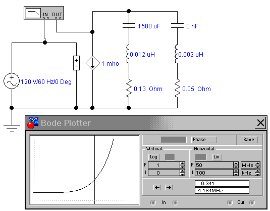
The 1500uF 250V electrolytic alone. It's 40mm D and 50mm H with 10mm pin spacing (for PCB mount).
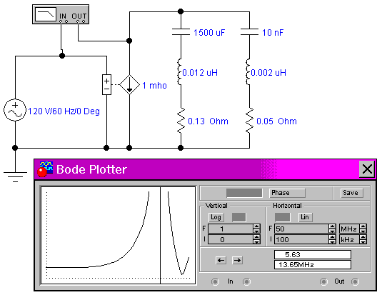
Adding 10nF 500V ceramic chip in parallel, what a disaster. Imagine all those naive people so proud of their 10nF bypass caps... Impedance is only low at 35Mhz.
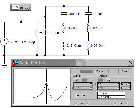
Adding 100nF 500V ceramic chip in parallel, not so bad, but these high voltage chips are very expensive and impedance at 4Mhz is still twice as high as with the electrolytic alone. In practice any impedance peak like this translates into ringing, excess EMI in SMPS, distortion in class-D and instability in audio power amplifiers.
Do you really need very low impedance at 10Mhz and above at the expense of messing things up in the 4Mhz range? Maybe in a RF transmitter, but never for audio.
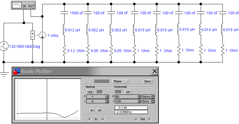
This is a more or less optimum solution with class-D and SMPS in mind, the most demanding applications. Two 100nF chips are required in order to get low impedance up to 50Mhz. Also, five 100nF film capacitors with 1ohm resistors in series are required to tame the resonant peak around 3Mhz (SMD chips are too expensive to use so many).
The root of the problem is exactly the fault that we are trying to solve: Inductance. The series inductance of any capacitor (not just electrolytics) will resonate with whatever other capacitor you put in parallel. You can assume 1nH per mm of pin spacing. A large-can electrolytic with 10mm pin spacing soldered to a PCB usually exhibits 10nH to 15nH. A film capacitor with 15mm terminal spacing exhibits approx 15nH too. Bigger films with 40mm or 50mm spacing exhibit approx 50nH (they are completely useless for bypassing). SMD chips may exhibit 2nH or so.
There is no rule of thumb for capacitor paralleling, every system has to be analyzed as the RLC elements it's made of. Then a custom solution that "complements" the existing RLC values is easily found.
Finally, note that I'm assuming that all the capacitors are mounted very close together in a double sided PCB with ground and power planes, with the load (be a class-AB amp, a class-D amp or a SMPS) sharing the same PCB and very close to the capacitors so that path inductances become negligible.
Even just 2 cm of wiring or conventional PCB tracks (with no ground or power planes) will add enough series inductance (5nH per 1 cm) to render any "remote" bypassing useless.
There is nothing more useless and ridiculous than all those remote capacitor boards (with all sorts of bypasses) traditionally used in class AB amplifiers. This can only come from people having zero understanding about high frequency electronics. Every 3 cm of wiring (approx 15nH) is as inductive as a big electrolytic capacitor.

The 1500uF 250V electrolytic alone. It's 40mm D and 50mm H with 10mm pin spacing (for PCB mount).

Adding 10nF 500V ceramic chip in parallel, what a disaster. Imagine all those naive people so proud of their 10nF bypass caps... Impedance is only low at 35Mhz.

Adding 100nF 500V ceramic chip in parallel, not so bad, but these high voltage chips are very expensive and impedance at 4Mhz is still twice as high as with the electrolytic alone. In practice any impedance peak like this translates into ringing, excess EMI in SMPS, distortion in class-D and instability in audio power amplifiers.
Do you really need very low impedance at 10Mhz and above at the expense of messing things up in the 4Mhz range? Maybe in a RF transmitter, but never for audio.

This is a more or less optimum solution with class-D and SMPS in mind, the most demanding applications. Two 100nF chips are required in order to get low impedance up to 50Mhz. Also, five 100nF film capacitors with 1ohm resistors in series are required to tame the resonant peak around 3Mhz (SMD chips are too expensive to use so many).
The root of the problem is exactly the fault that we are trying to solve: Inductance. The series inductance of any capacitor (not just electrolytics) will resonate with whatever other capacitor you put in parallel. You can assume 1nH per mm of pin spacing. A large-can electrolytic with 10mm pin spacing soldered to a PCB usually exhibits 10nH to 15nH. A film capacitor with 15mm terminal spacing exhibits approx 15nH too. Bigger films with 40mm or 50mm spacing exhibit approx 50nH (they are completely useless for bypassing). SMD chips may exhibit 2nH or so.
There is no rule of thumb for capacitor paralleling, every system has to be analyzed as the RLC elements it's made of. Then a custom solution that "complements" the existing RLC values is easily found.
Finally, note that I'm assuming that all the capacitors are mounted very close together in a double sided PCB with ground and power planes, with the load (be a class-AB amp, a class-D amp or a SMPS) sharing the same PCB and very close to the capacitors so that path inductances become negligible.
Even just 2 cm of wiring or conventional PCB tracks (with no ground or power planes) will add enough series inductance (5nH per 1 cm) to render any "remote" bypassing useless.
There is nothing more useless and ridiculous than all those remote capacitor boards (with all sorts of bypasses) traditionally used in class AB amplifiers. This can only come from people having zero understanding about high frequency electronics. Every 3 cm of wiring (approx 15nH) is as inductive as a big electrolytic capacitor.
Eva said:Forget all this pseudo-scientific analysis, it's all wrong. Time is continuous and all possible delays come from transmission line effects only, which you may consider negligible for very short distances. Output current will come from *all* components at *all* times, it's only the ratio what changes depending on time and stimulus.
You have to learn to model everything as R, L and C elements and check impedance in the frequency domain. Results may seem a bit counter intuitive at first, but it's the only way to predict exact circuit behaviour.
For example, a small film capacitor in parallel with an electrolytic capacitor not having high ESR will actually result in higher overall output impedance, ringing and very bad performance in the low Mhz range.
The other way to learn about the subject is to build a current pulse generator with very fast rise and fall times and use it to see the actual pulse behaviour for whatever circuit configuration you want on the oscilloscope. I use to check my class D and SMPS designs that way.
ho, ho, ho ....
All this shunting electrolytic power supply caps with smaller film caps
is just waste of money. It does no good!!
I have tried to post this OPINION ( actually a FACT ) before.
But when a myth comes into roll among those believers
it is hopeless to try to kill it off 😀
If you do not take Eva word for it,
we have Rod Elliott explaining the same thing.
.. and they are not the only ones that say this.
Paralleling of electrolyts with film caps is total nonsense
from any scientific viewpoint.
Regards to Eva 🙂
Lineup
Appendix A.
------------------------------------------------
Here is from Rod Elliott website
http://sound.westhost.com/articles/capacitors.htm
In a real circuit, there is a possibility that a small film capacitor in parallel with a large electrolytic may cause ringing (damped oscillation) at a frequency determined by the series inductance of the electro and the capacitance of the additional film cap.
This is more likely to degrade performance than improve matters.
It is possible to simulate this easily, but it is not so easy to measure because the frequency will be very high, and the impedance still very low.
Because this possibility is rather remote, if it makes you feel better, by all means add a parallel film cap.
Don't expect to hear a difference in a blind test though, because you almost certainly will not.
The pulse response is interesting.
This is as close as I could get to the actual measured waveform,
and contrary to common belief,
adding a parallel capacitor (in this case 220nF)
did not change the measured pulse waveform one iota.
The impedance of the film cap is simply much higher than that of the electro,
so it cannot have any significant effect on the end result.
There is an effect, but it is immeasurably small.
.
lineup said:
ho, ho, ho ....
All this shunting electrolytic power supply caps with smaller film caps
is just waste of money. It does no good!!
It's not always that way. It's just circuit design, it's all about component values. The wrong ones can ruin a circuit.
There are very few optimum capacitor combinations, often involving several capacitors and resistors, that yield a nice flat impedance curve up to 50Mhz, like in my example. Then we have the rest of combinations, the simpler and most common ones, that do more harm than good. Fortunately, audio circuits are so forgiving... 😀😀😀
Is there an alternative meaning to the word "ADD" ?
Golam
Please note that I wrote:
"I have added 6uF Kimber Caps to my 100 watt class A amp"
Adding means ADD.
Last night I swopped the caps with 12 uF of another brand and once again the sound changed drastically. Much more 3 dimensional sound but slightly too much bass. The trick is obviously to find the correct make and value for a particular amp.
Years ago I added a single 2 uF to a DIY Aleph 30 PSU and it tightened up the bass incredibly - however I suspect that was a pure fluke.
Any recommendations re what value's to use on a caps of 40-000 uf x 2 per side will be appreciated.
Regards
JH
Eva said:
It's not always that way. It's just circuit design, it's all about component values. The wrong ones can ruin a circuit.
So what you say, Eva
is that I should start bypassing my power supply 10.000 uF with parallel 100nF polypropylene.


Well, let me have my serious doubts .... 😉
Every time I see the word snubberize in this forum or elsewhere,
it makes me feel real sick 😀
In fact, film capacitor or smaller electrolyts bypassing
I prefer to use much closer to the audio circuit.
Where I think they will do any good.
See my attachment
for how I suppose we should use those capacitors we have bought.
😀 😀
... I really do not expect any reader to agree ....
but I post it anyway.
Somebody may get my point .. eventually
Attachments
Hi, EVA,
Thanks for the explenation 😀
For real components, how can we measure the R, L, C of a film or elko capacitor? Is there a practical measurement method we can use at home?
Thanks for the explenation 😀
For real components, how can we measure the R, L, C of a film or elko capacitor? Is there a practical measurement method we can use at home?
Measuring the ESL of electrolytic capacitors is quite easy. Connect a small film in parallel and find out the resonant frequency. Remember that lead lenghts are critical. Then solve this:
Fr=1/(2*3.1415*sqr(ESL*C))
Where:
Fr is the resonant frequency
C is the value of the small film capacitor
To measure the ESR of electrolytics at high frequencies fed them with a 1Khz to 1Mhz square wave through (non-inductive) resistors (so that it essentially acts as a current source) and take a look at the voltage drop across the capacitor. Then calculate ESR as in a voltage divider.
Hi Eva,
Thanks.
Post 10 is one of the most informative you have given us, because you took the time to explain and show what we need to understand.
Now,
can I ask you to start a thread on building that pulse generator?
Thanks.
Post 10 is one of the most informative you have given us, because you took the time to explain and show what we need to understand.
Now,
can I ask you to start a thread on building that pulse generator?
lineup said:
Every time I see the word snubberize in this forum or elsewhere,
it makes me feel real sick
Well, OnSemi, Fairchild, etc., manufacturers of diodes, don't sell capacitors (except, perhaps, Vishay) -- and they all have white papers on "snubberizing" the diodes of the power supply.
Simulations are nice, I confess to being addicted to them ... but we also need bench tests... I knocked down quite a bit of noise which was coming through from a Dell laptop computer power supply by bypassing the electrolytics.
Without pseudo-scientific analysis.
Very interesting, academic, threadbare, in depth and deliberate analysis regarding bypass capacitor generating lot of food for thought.
In linear circuits, most of the cases small ceramic/plastic /film capacitors are used, termed as bypassing capacitor and the circuit is working for years without any noticeable disturbance and users are happy. Those ceramics/plastic/film capacitors are not required according to simulation. But renown company's are using and the circuit is adopting and tolerating those useless capacitors. Adaptability and tolerance is the essence of life and also very much applicable in the electronics field. If the circuit can tolerate those, it proves that practical parameters probably requires some modifications as all the simulations may not be applied in toto in practical field.
For Professionals,
In smps circuits, only electrolytic capacitors can not preform alone as with the increase of heat and frequency, high frequency high voltage spikes reduce the electrolyte and increase the ESR value. So, only electrolytic capacitors can not make the circuit stable and there is every possibility that circuit fails. So, low ESR, low impedance, higher ripple ratings and greater life ratings at higher temperature ceramic/plastic/film capacitors are required with electrolytic capacitors. These capacitors have very low temperature coefficients and have very high tolerance on capacitance value compared to the electrolytic capacitors. For that reason, in all smps circuits, these capacitors and electrolytic capacitors are used side by side to stabilize the circuit and ensure proper functioning. But proper combination is required and without calculation/combination nothing can be used in life, what to say about Power Electronics. Random sampling and use is not for professionals and only for newbies for test and trial purpose.
Soft and peaceful simulation in home requires adaptability in harsh practical/industrial environment and hence all Electronics Professionals may not fully agree with software simulation only, where practical hundreds of parameters are absent.
Rod Eliott is a respectable and knowledgeable man but his saying can not be the last word in Power Electronics/smps.
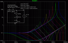
Adding to EVAs's excellent comments, I'd like to repost a simple simulation I posted here quite a while back, when this topic was already discussed "to death".
This is what happens to the output impedance when the bypass doesn't perfectly match the cap to be bypassed, including wiring inductance etc. These are the exact same resonant frequencies that EVA's ESL equation describes.
The red line is the optimum case, that is when the condition
C=4*ESL/ESR²
is satisfied (which is just another way to write EVA's equation, making some things more explicit, like not neclecting the bypasses ESR).
C is the bypass capacitor, ESL the total series inductance it sees, comprising the master cap's ESL and wiring inductance ahead, and ESR s the sum of both cap's ESR's. Now both ESR and ESL are ill-definded (one needs to measure them in situ), and ESR is used squared, increasing the uncertainity and therefore it can quickly happen that the bypass is to small, then we see the impedance peaks in the problematic region of 1...10Mhz. And this is only a simulation of first order effects, in reality it tends to be more complicated.
Bottom line, only bypass when the ESR of the cap to be bypassed is known and rather large, and try to go on the "too large" side.
- Klaus
Attachments
- Status
- Not open for further replies.
- Home
- Amplifiers
- Power Supplies
- Is bypassing PSU capacitors effective?
