I've seen many high end amplifier topologies here use a DC servo. Is it really that necessary to include this in a high end design? I'd rather eliminate the offset voltages by using high quality components and calibration as a servo seems like a patch rather than addressing the cause of the problem. For example using a differential op amp at the input whose common mode voltage can be adjusted would help.
H
HAYK
If the amp is current feedback, servo is necessary. The difference with servo, it provides second order high pass instead of first.
Hi,
I have a question not about their usefulness but related to servo:
If you have multiple stage using them in serie ( let's say a line input receiver, a gain stage and a line driver- line level gear) how would you manage fc of each loop?
I think it not wise to have the same one ( fc) for each stage as it could lead to instability(?) But i might be wrong...
So how would you specify these fc for each stage? Is there a rot?
If they need to be different then how would one order them?
From lowest fc to highest? Highest to lowest? Doesn't matter?
I agree with comments above—- it’s quite possible to achieve acceptably low DC output without resorting to use of a DC servo. But low DC error isn’t the sole incentive/benefit for the servo.
Most designs reduce power amp gain to unity at DC and generally use a large electrolytic cap (tens to hundreds uF) to set the high-pass corner frequency and this cap is often regarded with high suspicion re distortion. A servo allows the high pass to be established with a relatively small, low-distortion film cap.
Most designs reduce power amp gain to unity at DC and generally use a large electrolytic cap (tens to hundreds uF) to set the high-pass corner frequency and this cap is often regarded with high suspicion re distortion. A servo allows the high pass to be established with a relatively small, low-distortion film cap.

You have to keep the DC offset under control somehow. A DC servo is one way of doing that, a method that's predictable and has the advantages that BSST pointed out, but you can use whatever method you like.
Hi,
I have a question not about their usefulness but related to servo:
If you have multiple stage using them in serie ( let's say a line input receiver, a gain stage and a line driver- line level gear) how would you manage fc of each loop?
I think it not wise to have the same one ( fc) for each stage as it could lead to instability(?) But i might be wrong...
So how would you specify these fc for each stage? Is there a rot?
If they need to be different then how would one order them?
From lowest fc to highest? Highest to lowest? Doesn't matter?
I don't see why there would be instability. When you have second-order loops, you can use each loop to make a pole pair of a high-order Butterworth filter and get a ridiculously flat magnitude response, if you want to.
A disadvantage of having many high-pass sections in a row, no matter whether they are made with DC blocking capacitors or servo's, is that the phase shift for the lowest bass frequencies gets worse and worse, and also the magnitude response when you don't design the whole chain to become one big Butterworth filter.
Hi,
I have a question not about their usefulness but related to servo:
If you have multiple stage using them in serie ( let's say a line input receiver, a gain stage and a line driver- line level gear) how would you manage fc of each loop?
I think it not wise to have the same one ( fc) for each stage as it could lead to instability(?) But i might be wrong...
So how would you specify these fc for each stage? Is there a rot?
If they need to be different then how would one order them?
From lowest fc to highest? Highest to lowest? Doesn't matter?
Multiple device, each with its own servo, would not act any differently than simple stages with more common series blocking caps.
Just saw Marcel’s post. What he said. 😉
The electrolytic capacitor in the feedback loop has negligible reactance at 20Hz. Any non-linearity gets diluted by the reactance being small.
I recently measured my amplifier at 0.4mV DC offset. This is with the large capacitor, offset null trimpot, and discrete bipolar transistors.
Ed
I recently measured my amplifier at 0.4mV DC offset. This is with the large capacitor, offset null trimpot, and discrete bipolar transistors.
Ed
Regarding equal time constants and instability: in valve amplifiers with overall negative feedback across several AC coupled stages, the AC coupling time constants are often chosen to be very different in order to keep the overall feedback loop stable. That is not applicable at all to a cascade of amplifiers with no feedback from the last to the first.
What high quality components, though? Not passives. The dc drift is mostly caused by transistor thermal drift, changes in current gain and turn-on voltage, all around the circuit. I guess you could devise a very accurate, discrete circuitry where these effects are largely cancelled out but then you would probably have an instrumentation amplifier rather than a power amp. Or you would need to use a high precision op-amp as the input stage.I've seen many high end amplifier topologies here use a DC servo. Is it really that necessary to include this in a high end design? I'd rather eliminate the offset voltages by using high quality components and calibration as a servo seems like a patch rather than addressing the cause of the problem. For example using a differential op amp at the input whose common mode voltage can be adjusted would help.
IIRC, didn't Doug Self find that if the voltage drop across eletrolytics he tested was less than ~65mV then there was no noticeable HD? Of course HD/THD aside, some electrolytics may produce some signal-correlated noise as a function of current flowing through them. There may be linear distortion effects as well (e.g. possibly audible linear wave shaping of LF transients). Not sure that nonlinearity is the only thing that can matter, is all.Any non-linearity gets diluted by the reactance being small.
Markw4 - That is a good data point. It supports making the electrolytic large so that it does not develop much voltage drop.
I think the main downside is reliability. I avoid electrolytic capacitors as much as possible, but providing DC feedback seems to be a worthwhile use.
Ed
I think the main downside is reliability. I avoid electrolytic capacitors as much as possible, but providing DC feedback seems to be a worthwhile use.
Ed
Not only does a DC servo allow you to remove two capacitors (input, feedback) and their associated poles, it can also remove DC offset from the source.I've seen many high end amplifier topologies here use a DC servo. Is it really that necessary to include this in a high end design? I'd rather eliminate the offset voltages by using high quality components and calibration as a servo seems like a patch rather than addressing the cause of the problem. For example using a differential op amp at the input whose common mode voltage can be adjusted would help.
H
HAYK
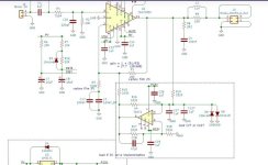
I think it's a trick to make a non-inverting integrator using only one capacitor in the signal path, I think "load C27 or C127" means that only one of them is mounted. A disadvantage is that you need good enough matching between R16, R17, R18 and R19.
It's only a pure integrator when R16/R19 = R17/R18, otherwise it's either a damped integrator or a circuit with a positive real pole. In the latter case, the integrator is unstable, but not the entire amplifier; you just get worse suppression of the offset, like with a damped integrator.
It's certainly original, I've never seen a negative-impedance converter in a DC servo before.
Last edited:
The attached schematic is from Parasound. I notice that they use two back-to-back zeners in series thus limiting op-amp input voltage to approx. +/- 12.5 volts as opposed to other implementation where the input is limited by two diodes in anti-parallel, limiting input voltage to about roughly +/-0.6 volts. What are the advantage of one over the other?

Is it in an amplifier?
If yes i think this is to protect the servo from potential overvoltage ( from amplifier stage which use higher voltage rail than servo's one): theorically the servo works on restricted voltage range to reduce dc compared to the 'amplifier stage core'.
If yes i think this is to protect the servo from potential overvoltage ( from amplifier stage which use higher voltage rail than servo's one): theorically the servo works on restricted voltage range to reduce dc compared to the 'amplifier stage core'.
Thanks, this makes sense.
Krivium: Yes this is from a Parasound A21 power amp (approx. 300w).
EdGr: So I guess the diodes will only serve to protect the servo from secondary damage in case the output stage is driven to full rail DC-voltage in case of a major failure of the output stage by limiting differential voltage on input 12-volts. I.e a couple of volts below the 15-volt supply used on the AD711.
The schematic in post #15 above uses D8 / D9 to limit the diff voltage to +/- 0.6 volts on the TL071 input, guess one solution is as good as the other.
I also notice that Erno Borbely does not use any such protection diodes on his Servo-100 design published in TAA back in -84 (using the LF411 as servo).
- Home
- Amplifiers
- Solid State
- Is a DC servo really needed