I’ve always been curious about these diodes. They always seem unnecessary, as the the maximum available fault current is often only a few tens of uA and I’ve yet to find an opamp that couldn’t tolerate the input current within its max specs. Possible leakage in these diodes seemed an unnecessary vulnerability.
On line level studio gear they are most of the time omited.
I think i've seen them used on GML's gear where there is different rail voltage for Discrete Operational Amplifier ( +/- 24v) and servo's AOP (+/- 15v).
I think i've seen them used on GML's gear where there is different rail voltage for Discrete Operational Amplifier ( +/- 24v) and servo's AOP (+/- 15v).
There are two other things to consider:
1. Some op-amps have polarity inversion issues when the input voltage goes out of the specified common-mode range. The diodes or Zener diodes prevent that.
2. For the circuit of post #15, the designer may have been worried about what could happen if the positive feedback is slightly stronger than the negative feedback. I don't see how anything could go wrong as long as the main amplifier has a higher output voltage range than the op-amp, though. Then again, that requirement is maybe not met during start-up and shutdown.

I think issue 1 is part of the reason: from the AD711 datasheet:
The other reason is to prevent cascade failure of the opamp should the outputs hit the rail - always good design to limit the spread of damage from known failure modes. Although the 1M resistor is likely good enough on its own as the AD711 is not CMOS inputs.
But these days no-one ever needs to use such opamps.Typically exceeding –14.1 V negative common-mode voltage on either input results in an output phase reversal.
The other reason is to prevent cascade failure of the opamp should the outputs hit the rail - always good design to limit the spread of damage from known failure modes. Although the 1M resistor is likely good enough on its own as the AD711 is not CMOS inputs.
If it had CMOS inputs, it would have ESD protection that would probably cause it to survive (although that depends on the kind of protection circuit).
Last edited:
The front end diamond buffer transistors Vbe's cancel, leaving just an offset component arising due to normal production spread transistor Vbe differences that can easily be dialled out using a simple pot and series resistor. What is left are the differences in dVbe of c. -2.2mV/C which also cancel leaving just the ddVbe's which in practical terms are worst case 10's of uV/C - of no consequence in a power amplifier. The kx2-Amp has an initial offset on my build of 10mV that drops to under 1mV after 2-3 minutes and is never more than +-5mV over time and temperature. You should conclude from this that CFA'a do not need a servo. See example below for typical implementation - Q9, Q10, Q5 and Q8 must be in close thermal proximity.If the amp is current feedback, servo is necessary. The difference with servo, it provides second order high pass instead of first.
Servo's are useful in VFA's where you may choose to avoid using a large DC blocking capacitor in the lower leg of the feedback network. In a CFA, the feedback network is almost always DC coupled because Rf is usually not more than 1k and Rg usually a few 10's of Ohms and is part of the compensation design. If you wanted to AC couple this, it would entail impracticably large capacitor values.
🙂
Doing a CFA design forced my hand to use a servo. Glad it happened. was able to adapt my VCCS (voltage controlled current source) to a VFA , as well.
Built both versions and even forgot to hook the servo up once. All that happened was the Vbe differences of (a diamond) reared it's ugly head. Servo
failure , either rail .... just offsets the VCCS by less than .5mA. Contrary to what some say , this VCCS is NOT in the audio path. Circuit PSRR absorbs any
garbage.
VFA (Leach amp - below 2) is just as easy to implement. VCCS does the same as adjusting one of the current sources - as in my non-servo'ed edition.
Performance is stellar and fault proof - 1-2ppm @ 1hz , offset in the uV range.
Both these designs , I can eliminate any electrolytic's , 2.2uf 16-25V's (for the regs and servo)can be Kemet ceramic SMD. Tiny precision IPS's.
PS - I would not touch a servo applied in the typical manner. I HATE servo's !!!
EDIT - VFA is inverting , because it is a typical LTP. CFA is a positive servo. Doesn't matter since it is CCS based control. Servo quality really doesn't matter either.
Attachments
Instant ... or close to it. Dependent on the servo R/C , as well. I've noticed these designs can even run right down to DC (without the input cap).
Whatever gets through the HPF (servo) is just cancelled the same as rail ripple would be at the CCS's.
"Settling" is not much of a factor here , this works differently than most servo implementations.
Whatever gets through the HPF (servo) is just cancelled the same as rail ripple would be at the CCS's.
"Settling" is not much of a factor here , this works differently than most servo implementations.
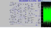
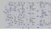
Regarding cfa servo.jpg:
Are you sure it doesn't just seem to settle quickly because the initial offset is already too small to do any harm? Do you notice any difference when you just ground the node R9-R10?
It looks like a first-order DC feedback loop to me: the output voltage goes into an integrator with 2.2 s time constant, its output signal gets attenuated by voltage dividers consisting of R7 ... R11, the attenuated signals get converted to currents by voltage-to-current amplifiers with R12 and R15 as feedback resistors, these currents cause voltage drops across R13 & Q3 or R14 & Q4 and the resulting voltage gets amplified by a factor of R16/R19 + 1 = R17/R20 + 1 and goes back to the integrator. Transistors Q3 and Q4 appear to be biased at about 2 mA, so their emitter resistance is about kT/(qIE) ~= 13 ohm.
The time constant of the whole loop is increased by every attenuation and decreased by every amplification, so it should be about
2.2 seconds * (1 + 3*6800 ohm/100 ohm) * (680 ohm/(33 ohm + 13 ohm))/(1 + 820 ohm/33 ohm) ~= 257.92 seconds (rough estimate)
Settling to 5 % of the initial offset should take about 772.67 seconds, more than 12 minutes. The cut-off frequency should be about 617 uHz.
Marcel, the un-servoed offsets in most cases are just a few hundred mV and once the servo settles initially pose little problem thereafter since the servo -3dB is << 1Hz. Do you have a practical example of how this affects audio performance negatively? Serious question btw - I used a servo in a commercial amp and measured no difference in distortion (< 7 ppm at 200W out).
“Settling to 5 % of the initial offset should take about 772.67 seconds, more than 12 minutes. The cut-off frequency should be about 617 uHz.”
But surely you have to consider that the servo amplifier output can go to +-12 V. I can turn my servoed amp on and it’s settled to +-4mV in seconds- definitely not the 12 minutes you are suggesting.
But surely you have to consider that the servo amplifier output can go to +-12 V. I can turn my servoed amp on and it’s settled to +-4mV in seconds- definitely not the 12 minutes you are suggesting.
You probably use a different circuit than ostripper.
In any case, my calculation is a small-signal calculation, so I don't take into account the extra settling time that you get if something should clip.
In any case, my calculation is a small-signal calculation, so I don't take into account the extra settling time that you get if something should clip.
My main concern would be what happens in the loudspeaker. A DC offset could increase the even-order distortion of the step-up transformer of an electrostatic loudspeaker or could increase the even-order distortion of a dynamic loudspeaker by moving its cone from the intended rest position.Marcel, the un-servoed offsets in most cases are just a few hundred mV and once the servo settles initially pose little problem thereafter since the servo -3dB is << 1Hz. Do you have a practical example of how this affects audio performance negatively? Serious question btw - I used a servo in a commercial amp and measured no difference in distortion (< 7 ppm at 200W out).
I have no idea how bad an offset has to be for these effects to become measurable. I'm pretty sure a couple of millivolts is so many orders of magnitude below the levels a loudspeaker normally has to handle that it will be no issue, but at what offset levels it does become an issue?
Last edited:
In addition to this: Depending on the circuitry on the primary side, an ESL can have very low DC resistance (<<1 ohm). A DC offset of 30 mV can result in a DC current that exceeds the idle current of the output stage.A DC offset could increase the even-order distortion of the step-up transformer of an electrostatic loudspeaker
I generally use a TLO71/2 which gives worst case +-4mV offset if I am using a servo. I’ve never measured anything worse than 2mV.
My experience has been the same as Bonsai's. I typically use a first order loop with a time constant of around 1 second. [Note that the loop time constant may not be the same as the integrator time constant.] This settles to within 1% of its final value in approximately 5 seconds. The closed loop bandwidth is 0.159 Hz which is more than two orders of magnitude below 20 Hz. I have not been able to measure any increase in THD at 20 Hz with the servo engaged.But surely you have to consider that the servo amplifier output can go to +-12 V. I can turn my servoed amp on and it’s settled to +-4mV in seconds- definitely not the 12 minutes you are suggesting.
This is a fine solution for almost any situation. For those who want even less offset, there are FET input op amps with better DC offset specifications, or a trim adjustment could be added.I generally use a TLO71/2 which gives worst case +-4mV offset if I am using a servo. I’ve never measured anything worse than 2mV.
True, found a spare AD744 and have used that along with some surplus 1uf styrene caps in my dac. Haven’t had a reason to try anything else. I know it shouldn’t even require the overkill, but…
Same basic circuit with 100k on the input.
Same basic circuit with 100k on the input.
Just in case there are still misunderstandings about it: my comment about greater than 12 minute settling times in post #30 applies only to the first circuit of post #27, which I estimated to have a 617 microhertz cut-off frequency. When you design for a much higher cut-off frequency, settling goes much faster.
Last edited:
- Home
- Amplifiers
- Solid State
- Is a DC servo really needed