Hi All,
When I realized that switching amp can be better than most linear amps, I started thinking about building my own Class-D amp. It's gonna be my first Class-D project after few Class-A / AB amps projects that I've designed. I still don't know whether pre- or post-filter feedback design is better, so in this design I can try both (I hope so).
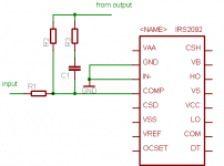
As it's my first class-d amp, I decided to use reference design from IRS2092 datasheet and add opportunity of selecting post-filter feedback by jumpers. Maybe it's possible to use both feedback paths, but now I'm only in the beginning.
Could you please comment it as it's my first switching amp project.
Every opinion is welcome.
Please see attached schematic and PCB layout.
When I realized that switching amp can be better than most linear amps, I started thinking about building my own Class-D amp. It's gonna be my first Class-D project after few Class-A / AB amps projects that I've designed. I still don't know whether pre- or post-filter feedback design is better, so in this design I can try both (I hope so).
As it's my first class-d amp, I decided to use reference design from IRS2092 datasheet and add opportunity of selecting post-filter feedback by jumpers. Maybe it's possible to use both feedback paths, but now I'm only in the beginning.
Could you please comment it as it's my first switching amp project.
Every opinion is welcome.
Please see attached schematic and PCB layout.
Attachments
The IRS2092 reference design works well (I have the dual-channel evaluation board from IR in front of me as I type), but I doubt if you will be able to make a stable post-filter NFB design using the 2092. The internal op-amp and comparator have internal connections that assume a self-oscillating sigma-delta design, with pre-filter NFB. When I first saw the internals of the 2092 I wondered if a UCD-style amp could be made using it, but this would require access to certain internal nodes that are not brought out from the chip. (I'd love some-one to prove me wrong about the inability to make a UCD topology using this chip though!)
Ouroboros,
I thought that COMP pin is output of comparator. It just depends on design whether it's sigma-delta or ucd like amp. The comparator has the same function as ucd input comparator, I believe 😕
I thought that COMP pin is output of comparator. It just depends on design whether it's sigma-delta or ucd like amp. The comparator has the same function as ucd input comparator, I believe 😕
Hi Darkone,
I have built an amplifier with IRS2092
(http://www.diyaudio.com/forums/showthread.php?s=&threadid=116056)
It works very well and it sounds very good.
Now I am planning a newer version with lower power and your idea of post-filter feedback is very interesting.
Your pcb layout looks good, BTW which voltage rails will you use on that amp?
IRS2092
Post filter feedback is impossible with this chip. The inegrator is not accessible.
The irs20955 is possible as the integrator is outboard
Stephen Mantz
Zed Audio Corp.
Post filter feedback is impossible with this chip. The inegrator is not accessible.
The irs20955 is possible as the integrator is outboard
Stephen Mantz
Zed Audio Corp.
DarkOne said:Ouroboros,
I thought that COMP pin is output of comparator. It just depends on design whether it's sigma-delta or ucd like amp. The comparator has the same function as ucd input comparator, I believe 😕
No!, the comp pin is the output of the transconductance amplifier used as the input stage in the chip. The output of this amp feeds the internal comparator. If the output of the transconductance amplifier and the input of the comparator were on separate pins, then a UCD amplifer might have been possible, but not as the chip stands at the moment (unfortunately).
I don't really understand you, guys! Why would be impossible to make a simple fast amplifier with OTA?
For the normal topology UCD amplifier the post-filter NFB has to feed into the input of the high-speed comparator stage (not the op-amp) and be summed with the audio signal from the input stage. It is possible to split the feedback route in a UCD by having part going directly into the comparator, and part going via the input op-amp to provide an active pole which increases the loop-gain at low frequencies, but you cannot have a single NFB connection into the input of the op-amp. This is different from a sigma-delta amplifier where the input op-amp is essentially an integrator.
The reason that I said earlier that it would be possible if the output of the OTA was brought out to a pin, and the input to the comparator was also on a separate pin, is that we could put a 1k (say) resistor between the output of the OTA and the input of the comparator and feed the NFB into the comparator input.
When I first saw the internals of this chip, and realised that the input op-amp was an OTA, having a high-impedance current output, I thought that it might be possible to connect the post-filter NFB to the COMP pin, but unfortunately, once you apply the required local NFB around the OTA, it decreases its output impedance which messes up the idea. (At least that is what SPICE tells me, using a simple model of the 2092).
Ouroboros said:For the normal topology UCD amplifier the post-filter NFB has to feed into the input of the high-speed comparator stage (not the op-amp) and be summed with the audio signal from the input stage. It is possible to split the feedback route in a UCD by having part going directly into the comparator, and part going via the input op-amp to provide an active pole which increases the loop-gain at low frequencies, but you cannot have a single NFB connection into the input of the op-amp. This is different from a sigma-delta amplifier where the input op-amp is essentially an integrator.
The reason that I said earlier that it would be possible if the output of the OTA was brought out to a pin, and the input to the comparator was also on a separate pin, is that we could put a 1k (say) resistor between the output of the OTA and the input of the comparator and feed the NFB into the comparator input.
When I first saw the internals of this chip, and realised that the input op-amp was an OTA, having a high-impedance current output, I thought that it might be possible to connect the post-filter NFB to the COMP pin, but unfortunately, once you apply the required local NFB around the OTA, it decreases its output impedance which messes up the idea. (At least that is what SPICE tells me, using a simple model of the 2092).
So, to implement ucd-like topology is not as easy as I thought. Maybe the better solution for ucd-like amp is to use IRS20955.
For the first time class-d project I would use something simple, maybe then I'll try to implement post filter feedback.
Thanks
Just for information, is it possible to make a combined pre and post filter feedback?
I am thinking about a feedback coming directly after the filter (1) combined with another one coming before the LPF (2).
Feedback (2) will be combined to feedback (1) trough an high pass filter having roughly the same cutoff as the output LPF.
In this case the pre filter feedback works to generate the oscillation and the second feedback is used to linearize the LPF response with different loads.
Has anyone tried something like this or is it just a stupid idea?
thanks
marco
As they say: "Open elements of PWM modulator section allow flexible PWM topology implementation."
You can do whatever you like, but UcD is the best. 🙂
If you make a pre+post filter feedback optimally, the resulted transfer function will be very similar to the one of UcD.
You can do whatever you like, but UcD is the best. 🙂
If you make a pre+post filter feedback optimally, the resulted transfer function will be very similar to the one of UcD.
This is unusable. Offset of OTA will affect it very much. +/-15 mV multiplied by 100 mS is +/-1,5 mA!
You can't disable OTA! You have to use it!
You can't disable OTA! You have to use it!
Pafi said:This is unusable. Offset of OTA will affect it very much. +/-15 mV multiplied by 100 mS is +/-1,5 mA!
You can't disable OTA! You have to use it!
Thats what I've been afraid of. It seems, that IRS20955 is more usable for all this stuff as I can change whether it's sigma-delta or ucd like topology outside the driver circuit
Thats what I've been afraid of.
Despite the fact that your scheme is a positive feedback at DC.
It seems, that IRS20955 is more usable for all this stuff...
Is there anybody who have seen my attached picture (and red the datasheet)?!? 😕
Pafi said:What's the problem with this?
Hi Pafi, I see that you use TINA Spice as well! Your simulated OTA using a VCCS has a first-order roll-off over the full frequency range. The built-in OTA in the 2092 is likely to have extra poles coming into play at frequencies well below the desired self-oscillating frequency, and so adding extra phase shift. I don't think IR have a SPICE model available for the IRS2092, otherwise it would be worth simulating to try out. The IRS2092 samples I have are surface-mount, so I can't knock up a simple test rig as I could if they were through-hole.
Ouroboros said:The built-in OTA in the 2092 is likely to have extra poles coming into play at frequencies well below the desired self-oscillating frequency, and so adding extra phase shift.
Maybe. I don't see any sign in the datasheet wich indicated extra poles. Do you? I saw this: "Open elements of PWM modulator section allow flexible PWM topology implementation." This implies the opposit! And an extra pole doesn't neccessarily ruin the feedback. You can compensate it, and some phase shift is not harmful to UcD, but neccessary!
If you really like to make UcD with IRS2092, then you shouldn't search for possible obstacles and give it up without checking if they are really exist!
- Status
- Not open for further replies.
- Home
- Amplifiers
- Class D
- IRS2092 customizable