There is no gain in circuit. So you are either loosing a few db on in or output (which is now debunked if you troubleshooted correctly), or the mystery lies somewhere else. What about the output transformers. Are both rotated the same way? And regarding pots: are both genuine and the same value?

However, perhaps one is linear and the other logarithmic
that would be funniest outcome ............

I have laid out my two balanced PCBs and the similar size transformers (haven’t ordered a pair with 18v secondaries yet or the metal enclosures). I can fit them in a 2U 330 wide x 230 deep Galaxy chassis. Transformers will be touching the power end of the PCB. Is that far enough distance between the signal and power transformers with Antek’s steel enclosures?
My balanced Iron Pre will be very simple. 1 SE in, 1 XLR and 1 SE out with no volume control. Volume control is done upstream along with input selection. Any way I could get a file for the graphic on the front of official chassis’s.
My balanced Iron Pre will be very simple. 1 SE in, 1 XLR and 1 SE out with no volume control. Volume control is done upstream along with input selection. Any way I could get a file for the graphic on the front of official chassis’s.
Is that far enough distance between the signal and power transformers with Antek’s steel enclosures?
no other way than to try
is there any way of mounting Donuts on side of enclosure, further from pcbs?
If you think pots are different it should even out at full output.
It should be easy to test if the "amp core" amplifies x2. E.g. 1000 Hz 1V RMS in and 2V RMS out.
Could it be that one channel is running in SE-mode and other in BAL-mode where you think both channels are in BAL-input mode?
Or maybe one of the JFET-buffers does not work as expected in "bad" channel?
It should be easy to test if the "amp core" amplifies x2. E.g. 1000 Hz 1V RMS in and 2V RMS out.
Could it be that one channel is running in SE-mode and other in BAL-mode where you think both channels are in BAL-input mode?
Or maybe one of the JFET-buffers does not work as expected in "bad" channel?
Both pots seem to have the same max/range. One channel gives almost full amplification at low volume setting. Could this be caused by a defective buffer? Voltages are in both channels 15v and 0 offset.
It's not the potentiometer, so it must be caused by something else. Maybe I misunderstood how to wire the input for SE? However, the issue is there with both SE and Balanced inputs.
How can I best verify the buffer stage?
How can I best verify the buffer stage?
JP1+ and JP- firmly in place?
Have a scope or a DMM?
In Bal mode
Send signal (any frequency with scope or 100 Hz with DMM) to input at pot pads.
Measure and calculate gain:
Just before Cinemags between JP- and JP+.
JP- to GND and JP+ to GND.
Measure at output between Out- to Out+;
Out- to GND; Out+ to GND
Make it go to SE mode
Take all the measurements again.
That should perhaps narrow things down.
My guess may not be the most elegant, or even correct, but that's how I'd try to get started if it were mine. It should only take a few mins, and it won't hurt anything even if I'm wrong.
What I'm trying to do is narrow it down...
Is it only SE or Bal mode? => check relay etc. if it's only one or the other.
Is it in the buffer? => should show weird gain between channels before Cinemag
Is it a bad joint or something with one of the Cinemags or something else after the buffer? => buffer will be fine, but will show off at output.
One channel gives almost full amplification at low volume setting
your wiring of something is to blame
now, instead of contemplating about religion, let's be practical
inject sine signal of 400Hz-1KHz in input
use regular DMM set to Vac to measure signal at back plate connector, then pot input, then pot out, then buffer out (jumper), then autoformer/pre output
say that input signal of 500mV to 1V, as seen on DMM is convenient
all said points, measurement ref. to GND, meaning black probe crocodiled to same
compare each point between good and bad channels
conduct measurements in mid pot position and in max pot position
Maybe I misunderstood
you have a camera - use it, after you do what I wrote above
Could be an option. Might leave a space of 25 mm. Will test out when I get my donuts.no other way than to try
is there any way of mounting Donuts on side of enclosure, further from pcbs?
@freebee
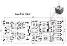
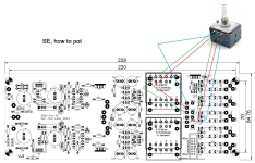
see this - Bal, how to pot
pretty much exact same logic for SE
do not forget - if having SE (RCA) input, you must solder small wire bridge between corresponding input pads GND and -IN, and also solder appropriate DI*
example, if Input 1 is going to be SE, small wire bridge between 1GND and -1, same as installed DI1, then RCA wired to 1GND and +1
edit: added SE, how to pot
Attachments
Last edited:
^ I'll put these in post #1. They might be useful for others. 
Hi ZM. I have my Iron Pre SE board running and singing beautifully! Thank you very much for making this project possible for noobs like me.
I am using a 20VA toroid (230VAC primary and dual 18V secondaries) to drive the Iron Pre and have 24V relays for switching between 2 inputs after you showed me how to do this with a toggle switch.
Now, a naughty question. Can I steal/draw some 500mA max from the (very clean well-regulated 24V) IP relay PSU to drive another device without ill effect? It is Pa’s FR EQ circuit. It will save me a 24V PSU.
I am using a 20VA toroid (230VAC primary and dual 18V secondaries) to drive the Iron Pre and have 24V relays for switching between 2 inputs after you showed me how to do this with a toggle switch.
Now, a naughty question.
Can I steal/draw some 500mA max from the (very clean well-regulated 24V) IP relay PSU to drive another device without ill effect? It is Pa’s FR EQ circuit. It will save me a 24V PSU.A quick question before I start building my SE board, if I do not want the gain of the autoformer can I eliminate it to get 0db gain? If so how do I go about doing it with the wiring. Idea is to first make the preamp without any gain to test with my setup and later if required add the cinemags for the gain 🙂
Thanks
Thanks
- Home
- Amplifiers
- Pass Labs
- Iron Pre Essentials Kits For The DIYA Store - Register Your Interest