Here is a teaser. Posting b/c it relates to fun topic of 2nd / 3rd etc. Also posting to show once again ZM brilliance and to confirm others' thoughts that yep, it is 3rd dominant for balanced... I ran a range of input voltages, and when I can actually measure the distortion... it starts off as 3rd and remains 3rd.
This is prototype Iron Pre V4 Super Mega Deluxe Balanced. It's in a chassis hooked up properly. Next up for today's fun... some listening.
Anyway... Ignore generator voltage noted. It is actually 250mV for a positive signal and 250mV for an inverted signal. So, input differential signal is 500mVrms. Output voltage is correct at 1Vrms differential between + and - signal.
Balanced in to Balanced out...
Yes, it's quiet...
Edited for clarity around word salad due to lack of sleep and need of more coffee.
Attachments
except one paying billif in doubt, use Lemo connectors, everyone happy
I hope they are.@MEPER
who sez they aren't?
I once used an XLR to RCA adapter on my DAC XLR out until I found out how it was wired (minus out connected to gnd).
I removed it when I noticed that. I guess those adapters are made for XLR in.
But now when it is possible to make that kind of errors it would be good design practice to have a 50R or 100R resistor from e.g. output from a opamp to protect the output.
I will find out when the BAL IP is ready if the XLR out on my DAC still works.
The Cinemag itself on IP will do the protection.
good design practice to have a 50R or 100R
we are talking of good engineering, or bad?
I think it is good.
Also for the manufactures not to have too many devices back for repair.
Especially for XLR-out which is a male with three pins sticking out. It is easy to do something "bad" 🙂
Also for the manufactures not to have too many devices back for repair.
Especially for XLR-out which is a male with three pins sticking out. It is easy to do something "bad" 🙂
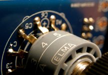
Ok, so I am thinking that I need a new Twister Board. Look at the connections. They are one off. Desolder? HA! Well, yes, I do have another Elma pot. This one will be destroyed when removed, and likely the Twister board won't look too good either. Interesting bends had to be made for this to work.
Attachments
I can give you mine, but how to get it back over the Atlantic to you 🤷♂️So, Twister Boards. Are they available? Yes/no
Will be much cheaper getting one from someone in the USA.
Thank you for your replies. I am going to look at this closer because even though it doesn't look right, I just ohmed out the switch by position, i.e. position 1 on the switch equals corresponding number on circuit board (1-5). Also, I notice that on the circuit board on each side of the header location is a + by the number 1, and a - by the number 5. These appear to be connected to what would have been position 6 of the switch. I will take another look at the schematic to better understand what this means, but I know that it is feeding the LED string, correct?
As to why I used the Elma switch in the first place, it was a matter of having them on hand, and I got them for practically free. Because they have a 1/8" shaft, it became another reason to use them up in cases such as this, since 1/8" cool looking knobs are harder to find.
As to why I used the Elma switch in the first place, it was a matter of having them on hand, and I got them for practically free. Because they have a 1/8" shaft, it became another reason to use them up in cases such as this, since 1/8" cool looking knobs are harder to find.
As to why I used the Elma switch
completely valid and logical - you had them, so opportunity was there
same as I had opportunity to pull your leg, couldn't resist

both Ry+ and Ry- are there on Twister, to enable LEDs
in first batch Switcher was distributing Ry+ to relays, second batch is changed, to distribute Ry-, matter of compatibility with logic circuitry (plenty of Boyz are Overgreedy)
Thanks to IAIMH, the parts are swiftly being per USPS. Got to admit, I do have one more of those fancy switches, but got a board and yup the proper switch on the way. I just have this thing about anything plastic opposed to anything metal. Yes, I get that they are just doing the basic no big deal switching here, but I am pretending that this will be the project of them all with no cost spared. I wonder if a Buster Brown shoe box would work for a chassis?
Depends if Ladies or Gent sizeBuster Brown shoe box would work
- Home
- Amplifiers
- Pass Labs
- Iron Pre Essentials Kits For The DIYA Store - Register Your Interest


