Hello, I've been "googling" and found this article on investment volume potentiometer. I was interested in the arguments. What do you think?. I would like to give their opinions. regards.
http://www.pcpaudio.com/pcpfiles/preamplificadores/previoinversor/previo inversor.html
http://www.pcpaudio.com/pcpfiles/preamplificadores/previoinversor/previo inversor.html
Last edited:
It appears to be a buffered, filtered active volume control. May have some minor advantages over a simple pot, but disadvantages too.
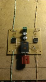
Well, I was intrigued enough to build it this weekend.
It seems simple enough for a dolt such as myself. I obviously over estimated my skills as I threw a meter on the output and was greeted by 385mV DC!
Grounding the input ground to the power ground dropped the DC to 85mV. Still way too high.
I went over my work but couldn't find anything. Now I am going to see if the circuit board corresponds to the published circuit.
I have never put anything together with perfboard, so at the very least, it was an enjoyable experience.
Attachments
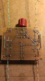
Update for the curious; Yesterday I fixed my screw-ups, which were failing to wire the op-amps in inverse order as per the schematic. Duh!
I threw the board into the temporary chassis and hooked it up. Nada. I think I killed the op-amps with my creative wiring. So, I ordered a pair of replacements which should be here next Monday.
I threw the board into the temporary chassis and hooked it up. Nada. I think I killed the op-amps with my creative wiring. So, I ordered a pair of replacements which should be here next Monday.
This is the way Bruno controles volume in his balanced pre-amp. The idea behind it is sound (both halves of the voltage divider have identical electrical characteristics). But in the actual application you will find some limitations of this approach.
So is Analog. Another gem of google translator. But you understood the concept, is not it ?. We could have put Inverter and we were all happy.
Greetings and I hope your opinion on the subject. Joseph.
Greetings and I hope your opinion on the subject. Joseph.
It appears to be a buffered, filtered active volume control. May have some minor advantages over a simple pot, but disadvantages too.
Low output impedance is a big advantage.
Complexity is a disadvantage. I don't think it would have a bad effect on the audio; if used to drive a long RCA cable the advantages would outweigh the disadvantages.
Driving the input of a circuit with a low pass filter on the input (like a power amp with an RF filter) with a potentiometer can cause problems. The output impedance of the pot (which varies with setting) can lower the cutoff frequency of the input filter. This effect can be intrusive.on the audio range.
Last edited:
I guessed that "investment" was something to do with the Thread opener getting ready to spend some hard earned money on an expensive volume control.
I never guessed he meant inverting !
I never guessed he meant inverting !
I've built a couple of buffered volume controls. Mine is simpler; just a unity gain buffer mounted on the board with the volume control. It uses only one DIP-8 dual op amp.
It works great if you need it, and saves space on the main board too. It mitigates any interference with the circuit being driven. Example, it drives a tone control board with adequate buffering. And if you build an inverting chip amp, you NEED an input buffer and this fits the bill.
It works great if you need it, and saves space on the main board too. It mitigates any interference with the circuit being driven. Example, it drives a tone control board with adequate buffering. And if you build an inverting chip amp, you NEED an input buffer and this fits the bill.
How are members of the forum. Although I have university education, my background is not English. Therefore, to avoid mistakes always I confirm what I write in English in the Google translator.
In this case, the translator played a trick on me, which I did not put that word confirmed and that has led to confusion.
I apologize to everyone.
But here it is important to know the English correctly and less important to argue that I do on the circuit of inverter volume, I think it is not worth continuing with this post.
Of course I will not change my amp Rotel placing this investment volume. The question was simply so that people who really know electronics give their opinions, and maybe do a test on some DIY circuit.
Fast Eddie D, I would like to know your circuit. We are here to provide ideas and circuits that work.
I was just looking for a simple to add to the phono preamplifier output buffer circuit that I built. Greetings.
I was just looking for a simple to add to the phono preamplifier output buffer circuit that I built. Greetings.
What is the output impedance of your pre-amplifier?
If it is capable of driving the interconnect cables then it is also capable of driving all normal domestic input impedances of 10k or greater.
If you plan to have a very low input impedance of <5k, then one may have to use a high current buffer. But that is fairly unusual.
If it is capable of driving the interconnect cables then it is also capable of driving all normal domestic input impedances of 10k or greater.
If you plan to have a very low input impedance of <5k, then one may have to use a high current buffer. But that is fairly unusual.
Andrew, I built several phono preamps: Muffsy; Solidphono; VSPS 300 of RJM. All with very good performance. But RJM advises and sells a buffer in order to improve and not to degrade the frequency response to take the integrated amplifier kit. As I not the fundamentals, I trust designers kits. Rotel has an input impedance of 50 kohms.
* Greetings and thanks for answering.
* Greetings and thanks for answering.
- Status
- Not open for further replies.
- Home
- Source & Line
- Analog Line Level
- Investment volume potentiometer