I see a fellow man of (photo) culture. Nice pics and nice overall analysis.photo setup
There is also a subjective aspect to which port artefacts are less bothersome. If the desired tuning frequency and length of the port is set as a constant (desired bass extension, cabinet size restriction), the choice is becomes having greater more gradual flare with a smaller cross-section in the middle or a less flared port with a greater cross section in the middle. These geometries have pros and cons in terms of the artefacts they produce.after the latest test results I thought about a possible reason to use slot ports.... cont
I'm still making some comparisons maybe I can add more later including some audio clips. Listening has been importaint for me where compromises must be made.
air particle displacement estimation
from the simulated peak air speed in the port (simulated in hornresp for two corresponding ports with the minimum and maximum diameter of the curved wall port) I calculated the theoretic displacement for air in a virtual tube port.In a curved wall port the air is being slowed down when travelling to a wider port section, so as a first very rough estimation I just took the arithmetic mean value (green numbers).
again, this is for the long progressive port, 50 Hz and 100 Hz (same graphs as in post #349, with added information):
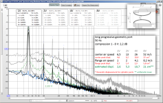
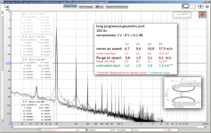
OK! now it's getting clear:
the low frequency turbulent flow in the port relates mostly to the displacement.
the 100 Hz fundamental and harmonic peaks start to widen up at 8 V, corresponding to an estimated displacement of 7,8 cm.
looking at the 50 Hz graph the widening of peaks will be similar a bit above 2 V (corresponds to 5,3 cm).
roozen writes about the strouhal number:
If the particle displacement approaches the order of the port radius [...] then there will be an unsteady separation of the acoustic flow at the port end, vortices associated with the separation of the flow will form, and jets will form.
In my experience this is a bit pessimistic, because I did not measure and hear compression or chuffing with a port measuring r = 1 cm in the center and r = 2,4 cm at the ends and particle displacement of up to 7,8 cm.
probably the noise was masked by my excitement ... 😊
Quick question, isn't this port tuned to 100Hz? So 50Hz would exhibit far different behaviour than at or above tuning.
Also maybe I'm being dumb (had a few beers tonight, worked all weekend!) but why does it matter physically if the displacement equals the minimum diameter of the port? Like why does that matter to the way the air flows longitudinally?
Also maybe I'm being dumb (had a few beers tonight, worked all weekend!) but why does it matter physically if the displacement equals the minimum diameter of the port? Like why does that matter to the way the air flows longitudinally?
here is the simulated and measured response (port 1 in cyan):isn't this port tuned to 100Hz?
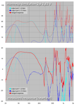
the small chamber with port 1 is tuned to about 70 Hz, but as this is a 6th order parallel bandpass there is output from about 50 to 110 Hz.
the max SPL is around 100 Hz, but the max port speed (and displacement) is at 50 Hz. I did not realize that myself and kept testing the max output frequency (100 Hz) instead of the max airspeed/displacement frequency (~ 50 Hz) until recently.
you deseved them!had a few beers tonight, worked all weekend!
this was introduced by strouhal and I guess there is no strict physical causality but a correlation caused by more complex mechanisms. It's probably just a rule of thumb.why does it matter physically if the displacement equals the minimum diameter of the port?
in my intuitive undestanding the directed air flow to the outside is separated because when air flows back into the port from the sides (thus -> radius) it separates (constricts) the air that still travels out and away from the port (port blowing).
... just a quick little teaser, prior to my small knee surgery tomorrow:
the 120 fps camera did provide some interesting results!
this was a first test, to confirm feasibility, using a cheap rented DSLR (canon 90D).
the more expensive 300 fps camera (panasonic GH6) comes next!
this is the setup:
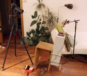
the laser is aligned to the port axis, the speaker and the laser are slightly rotated, so i can pour flour from above into the laser plane.
the camera is more or less perpendicular to the laser, because the macro lens has a tiny depth of field with the wide open diaphragm. this is necessary, because the laser has only 5 mW and the frame rate sets the limit for maximum exposure time.
as a first test i took three port openings of the lower tuned chamber two (35 Hz).
the ports have a 4 cm interior diameter cardboard tube and different port openings:

here come three short GIF excerpts of the videos, with 8 Vrms input (click thumbnails for animation!):
keep in mind that 8 V rms is quite high for this small woofer, air speed and displacement are also high (simulation results will follow!).
1 - hard edge:
no, no. no! we don't want to see that!!
actually, we don't even see the highest speed central "jet" created by the blowing port... particles are to fast!
2- rounded flange:

well, maybe a bit better, but there is still a lot of high air speed turbulence going on.
3- flared port opening:

YEESSS! this is better! oscillating particles from center to perimeter of the port! all particles seem to just travel forth and back. this is an ideal velocity-pressure transformer!
it seems incredible, also to me, but the input voltage was exactly the same for all videos!
and of course the visible turbulences were VERY audible!
I plan to edit a short video in full HD, showing port particle movement at different voltages and edit in the (real time) audio.
have a nice evening!
the 120 fps camera did provide some interesting results!
this was a first test, to confirm feasibility, using a cheap rented DSLR (canon 90D).
the more expensive 300 fps camera (panasonic GH6) comes next!
this is the setup:

the laser is aligned to the port axis, the speaker and the laser are slightly rotated, so i can pour flour from above into the laser plane.
the camera is more or less perpendicular to the laser, because the macro lens has a tiny depth of field with the wide open diaphragm. this is necessary, because the laser has only 5 mW and the frame rate sets the limit for maximum exposure time.
as a first test i took three port openings of the lower tuned chamber two (35 Hz).
the ports have a 4 cm interior diameter cardboard tube and different port openings:

here come three short GIF excerpts of the videos, with 8 Vrms input (click thumbnails for animation!):
keep in mind that 8 V rms is quite high for this small woofer, air speed and displacement are also high (simulation results will follow!).
1 - hard edge:

no, no. no! we don't want to see that!!
actually, we don't even see the highest speed central "jet" created by the blowing port... particles are to fast!
2- rounded flange:

well, maybe a bit better, but there is still a lot of high air speed turbulence going on.
3- flared port opening:

YEESSS! this is better! oscillating particles from center to perimeter of the port! all particles seem to just travel forth and back. this is an ideal velocity-pressure transformer!
it seems incredible, also to me, but the input voltage was exactly the same for all videos!
and of course the visible turbulences were VERY audible!
I plan to edit a short video in full HD, showing port particle movement at different voltages and edit in the (real time) audio.
have a nice evening!
Thanks @horn_power !Nice pics and nice overall analysis.
Hope you enjoy the latest animated pictures!
Thanks a lot @stv, for your time and effort on this study.
I am learning a lot from it. I have never seen this level of analysis and real-life visualizations of what goes on around a port design.
This is an awesome thread... 🙂
I am learning a lot from it. I have never seen this level of analysis and real-life visualizations of what goes on around a port design.
This is an awesome thread... 🙂
thanks for the pics and good luck with surgery!have a nice evening!
@stv So what you want to see is suspension of the particles in front of the port rather than transport of the particles by sucking and blowing? Would you be able to match a sound clip to each of the videos so we can hear the effect of what we are seeing?
This is an awesome thread...
Yeah, very nice!
good luck with surgery!
thank you very much for your kind and encouraging words from all around the world!Very cool stuff @stv!
the surgery went well, I'll be back on my feet soon!
sucking and blowing is just what the air in the port is doing. I want to reduce the speed of that motion as much as possible towards the exit to get a efficient (big surface) transformation to pressure outside the box.transport of the particles by sucking and blowing?
The problem with high port air speeds, big displacements and hard edges is that blowing tends to move into the center of the port ("jet" mentioned by roozen, i called it "blowing") but sucking happens at the port perimeter. This creates a steady airflowflow and turbulences (thus noise) and eats up precious bass energy.
Also, a hard bass reflex port edge will always create some small turbulence at this edge. Therefore noise and chuffing start already at low spl.
as the turbulences outside the port are quite chaotic (also see andy19191's explanation of vortex buildup - if i understand correctly) the noise has a quite even noise floor spectrum of straight hard edge port in post 349.
The vortex buildup inside the port for flared ports however is limited and guided by port expansion, thus seems to have a lower frequency spectrum, maybe related to helmholtz frequency, see same post (not yet sure about that).
That's the plan!match a sound clip to each of the videos
tuning frequency sine tones but maybe also some music.
a nasty chuffing noise at every bass drum beat completely destroys listening joy and makes you turn the volume down (and get sad).
a theory about bass reflex speakers:
maybe it's just the terrible port design (cheap straight tubes with the biggest possible surface to keep noise down) that ruins their sound and reputation?
So the "mission" here is to direct people's attention to the wrongly underestimated port and propose a sensible design.
(I am of course not alone and obviously not the first one ...)
Last edited:
Do you think you can get images of this strouhal effect? Or is that going to happen deeper in the port that can't be seen?
I am just working on that!you can get images of this strouhal effect?
just for the sake of pecision:
Strouhal - as far as I know - introduced the descriptive formula. Not sure if he also discovered the effect.
Edit: wikipedia article on the strouhal number
Last edited:
What was the tuning frequency of these ports?... just a quick little teaser, prior to my small knee surgery tomorrow:
the 120 fps camera did provide some interesting results!
this was a first test, to confirm feasibility, using a cheap rented DSLR (canon 90D).
the more expensive 300 fps camera (panasonic GH6) comes next!
this is the setup:
View attachment 1267172
the laser is aligned to the port axis, the speaker and the laser are slightly rotated, so i can pour flour from above into the laser plane.
the camera is more or less perpendicular to the laser, because the macro lens has a tiny depth of field with the wide open diaphragm. this is necessary, because the laser has only 5 mW and the frame rate sets the limit for maximum exposure time.
as a first test i took three port openings of the lower tuned chamber two (35 Hz).
the ports have a 4 cm interior diameter cardboard tube and different port openings:
View attachment 1267173
here come three short GIF excerpts of the videos, with 8 Vrms input (click thumbnails for animation!):
keep in mind that 8 V rms is quite high for this small woofer, air speed and displacement are also high (simulation results will follow!).
1 - hard edge:
View attachment 1267175
no, no. no! we don't want to see that!!
actually, we don't even see the highest speed central "jet" created by the blowing port... particles are to fast!
2- rounded flange:
View attachment 1267176
well, maybe a bit better, but there is still a lot of high air speed turbulence going on.
3- flared port opening:
View attachment 1267174
YEESSS! this is better! oscillating particles from center to perimeter of the port! all particles seem to just travel forth and back. this is an ideal velocity-pressure transformer!
it seems incredible, also to me, but the input voltage was exactly the same for all videos!
and of course the visible turbulences were VERY audible!
I plan to edit a short video in full HD, showing port particle movement at different voltages and edit in the (real time) audio.
have a nice evening!
With 120fps, you only have limited resolution. Anything above 60Hz will give problems.
Since the signal and camera (sensor) are out of sync, you can use averaging techniques over time to get a (quasi) better result.
35 Hz, port 2 of my 6th order parallel bandpass woofer.What was the tuning frequency of these ports?
That gives 3-4 frames per cycle, which is ok for a first feasibility investigation.
The third (flared port) gif animation shows it quite well, the oscillations are clearly recognizable.
The two other animations are more difficult to interpret, because airspeeds due to turbulent "blowing" is far too high and the particles already leave the picture after 1-2 frames.
A much improved video will follow soon.
Also, I will rent a 300 fps cam to catch particle movement more in detail.
After the first unsuccessful attempts with the humidifier (particles are too small) I now had very useful results showing turbulences with the humidifier mist. I'll include them in my video, thanks for the suggestion!Use ultrasonic humidifier to make ultrafine particles. Use a laser sheet (glass rod cylinder lens and green laser pointer) to make the light slice the plume.
Adding an audioXpress article to the collection:
https://audioxpress.com/article/how-good-is-your-port
https://audioxpress.com/article/how-good-is-your-port
- Home
- Loudspeakers
- Multi-Way
- Investigating port resonance absorbers and port geometries