Going back to this, and sorry if I'm being dumb, but are you saying there is physically no layer of near zero velocity air next to the port walls, or that typical boundary layer modeling solutions are not relevant?Not really because there are no boundary layers of much relevance involved. The Reynolds number is so low that a turbulence model is not applicable.
The velocity is zero at the wall and usually the steepest velocity gradient is at the wall though this can change as the flow diffuses or fails to diffuse and separates. The boundary layer of, say, a wing significantly influences the steady flow over the wing. The oscillating flow through a port is a Helmholtz resonance with what's going on near the walls having a minor secondary effect by introducing a bit of friction. The significant change to the discharge coefficient of the port due to a flare at the entrance isn't to do with what is going on next to the wall but changing the velocity profile in the middle of the port, the vena contracta, and hence how much pressure drop is required to drive the flow. A sharp flare at the exit will be too much for the flow to follow and it will separate creating vortices. A large gentle radius the length of the port may help the discharge coefficient a bit and what is going on next to the wall may have an influence here but a small one.
Boundary layer modelling and/or turbulence modelling is not applicable because the Reynolds number is small. The governing equations can be solved directly with what is going on near the walls fully resolved in time and space. This might need an appreciation of how and why turbulence models introduce approximate stresses into the governing equations which reduce the required resolution at high Reynolds numbers.
Boundary layer modelling and/or turbulence modelling is not applicable because the Reynolds number is small. The governing equations can be solved directly with what is going on near the walls fully resolved in time and space. This might need an appreciation of how and why turbulence models introduce approximate stresses into the governing equations which reduce the required resolution at high Reynolds numbers.

I may be on to something with the geometry as described in post 320.
well, it was to be expected, "elliptic shape ports" have been mentioned somewhere in the papers ... and many people already use them!
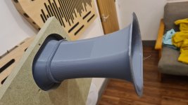
here is a rough (sic!) first chuffing comparison of small 3d-printed port (left) and the new "progressive curvature port" (right).
both ports have the same minimum diameter of 2 cm at the center. lenght is roughly the same.
the new progressive port has a bigger opening surface to the ends, thus the helmholtz tuning is slightly higher. the 100 Hz output is very similar however.
the new "progressive" port was printed standing up (thanks @augerpro for saving me some filament!) and I just joined the two halves with modeling clay, leaving the surface as it came out of the 3d-printer.

compare the light grey graph indicating the spectrum at 8 V:
the small 3d-printed port with a narrow radius opening has quite strong low frequency noise and the longitudinal resonance chuffing.
the new progressive curvature port has no low frequency noise and supposedly no "stalling" (which for the "small 3d printed port" also leads to longitudinal resonance buildup), but there is more very high frequency hiss, which for sure is the rough 3d-printed suface.
comparison of both geometries:

now I just have to find a correction factor for port tuning, compose a geometric formula (or is it just the elliptic curve?) and add the "latex resonance absorber" in the center. the main advantage of such a port will be the reduced dimension with subsequent reduction of resonance output and higher frequency port lenght resonance, ideally outside woofer pass band.
that's it. I found the perfect port! 😊
well, it was to be expected, "elliptic shape ports" have been mentioned somewhere in the papers ... and many people already use them!
here is a rough (sic!) first chuffing comparison of small 3d-printed port (left) and the new "progressive curvature port" (right).
both ports have the same minimum diameter of 2 cm at the center. lenght is roughly the same.
the new progressive port has a bigger opening surface to the ends, thus the helmholtz tuning is slightly higher. the 100 Hz output is very similar however.
the new "progressive" port was printed standing up (thanks @augerpro for saving me some filament!) and I just joined the two halves with modeling clay, leaving the surface as it came out of the 3d-printer.
compare the light grey graph indicating the spectrum at 8 V:
the small 3d-printed port with a narrow radius opening has quite strong low frequency noise and the longitudinal resonance chuffing.
the new progressive curvature port has no low frequency noise and supposedly no "stalling" (which for the "small 3d printed port" also leads to longitudinal resonance buildup), but there is more very high frequency hiss, which for sure is the rough 3d-printed suface.
comparison of both geometries:
now I just have to find a correction factor for port tuning, compose a geometric formula (or is it just the elliptic curve?) and add the "latex resonance absorber" in the center. the main advantage of such a port will be the reduced dimension with subsequent reduction of resonance output and higher frequency port lenght resonance, ideally outside woofer pass band.
that's it. I found the perfect port! 😊
Last edited:
Amazing what that tiny 3d printer surface roughness does in the top octaves of the chuffing noise.
there is another benefit of 3d-printing two port halves, besides the possibility to sand and smoothen the interior:

it allows to insert a port with two flanges through a "too small" hole!
some final smoothing of the joints would need to be done "on site".
it allows to insert a port with two flanges through a "too small" hole!
some final smoothing of the joints would need to be done "on site".
This is how I printed ome, split across the width, small flat flange for gluing and print bed ahesion. Allows one half to be flipped, so overhangs are all on the outside surface.
But your way does put the seam parallel to the flow, so maybe better 🤔
But your way does put the seam parallel to the flow, so maybe better 🤔
Attachments
corrected tuning with the "progressive port"
I used the same geometry method as described above, but adapted it's lenght, based on the tuning frequency with the (too) short progressive port:
the impedance measurements prove the tuning is correct. however, there are probably still some air leaks due to the preliminary play-dough mounting:

my chuffing measurment image seems to be lost, unfortunately, and I am travelling.
there was some resonant chuffing peak at around 2kHz, but I suppose this may also be due to turbulent air leaks.
I'll provide an update once I am back in my measurement lab, aka: my living room 🙂
Picture of the corrected and the too short progressive port shells:

Last edited:
long progressive geometry port, glued, sealed, sanded, smoothed:
impedance of the port as described above, but now air tight and with smooth surface:
just for comparison, the big 3d-printed port (about double length, see #310):

the smaller port has a slightly higher frequency middle peak at 8 V.
as seen before, the smaller cross section reduces the lower impedance peak (slight flow restriction).
however this could be an advantage as it reduces the unloaded cone excursion below the big chamber tuning!
response and chuffing measurements come next ....
response of correctly tuned (long) progressive geometry port:

for comparison the optimized "dual absorber big 3d printed port" and the "small 3d printed port" are included.
it is clearly visible that the big port transmits much more interior enclosure resonances between 400 and 1800 Hz, because the cross section is much bigger.
... chuffing measurement:

perfect!
no visible signs of chuffing, besides minimally widened fundamental and 2nd harmonic peaks!
even with 11,3 V signal (not shown here for better comparability) there is just a very small sign of beginning longitudinal resonance chuffing!
this confirms my hypothesis regarding the investigated case (with relatively low SPL) that chuffing is not related to the maximum air speed in the port center but only the critical transformation of pressure to velocity at the port ends. this is where noise and (of course) the longitudinal resonance are created.
it also proves that for home hifi use it will be possible to reduce the port size significantly and by doing so reduce transmission of all interior enclosure resonances and move the port resonances up.
the longer port as shown in post #328 (98 mm lenght, ~5 cm flange diameter, 2 cm center diameter) results in the same tuning as a 4 cm diameter port with 205 mm length - but much improved response, compression, chuffing... everything.
for comparison, here is once more the chuffing measurement of such a 205 mm long straight port:

next step: resonance absorber for the progressive geometry port!
Great work!
You inspired me to go back to the testing I did early in the year. I discovered the woofer was resonating on the baffle and that caused my test results to be affected. Woofer body braced and I'm seeing much more conclusive data.
I'll be posting my results in the near future, but I can say I've had some very good results going back to try the variable thickness port wall, thinning it out at the preasure peak of the main unwanted resonance. 😊👍 Variable Wall Thicknes port?
Glad to read that!You inspired me
And interesting to read about your findings!
For easy reference and comparison of geometry, would you be able to post a scale outsline drawing of the two ports being compared above?... chuffing measurement:
View attachment 1246371
perfect!
no visible signs of chuffing, besides minimally widened fundamental and 2nd harmonic peaks!
even with 11,3 V signal (not shown here for better comparability) there is just a very small sign of beginning longitudinal resonance chuffing!
this confirms my hypothesis regarding the investigated case (with relatively low SPL) that chuffing is not related to the maximum air speed in the port center but only the critical transformation of pressure to velocity at the port ends. this is where noise and (of course) the longitudinal resonance are created.
it also proves that for home hifi use it will be possible to reduce the port size significantly and by doing so reduce transmission of all interior enclosure resonances and move the port resonances up.
the longer port as shown in post #328 (98 mm lenght, ~5 cm flange diameter, 2 cm center diameter) results in the same tuning as a 4 cm diameter port with 205 mm length - but much improved response, compression, chuffing... everything.
for comparison, here is once more the chuffing measurement of such a 205 mm long straight port:
View attachment 1246375
next step: resonance absorber for the progressive geometry port!
I'm a little unsure exactly which one is the straight port mentioned.
apologies - I keep inventing names for the ports and it's probably difficult to keep track.I'm a little unsure exactly
I will do a big overview of the most important variants.
in the meantime here are the two ports mentioned in post 133:

- Home
- Loudspeakers
- Multi-Way
- Investigating port resonance absorbers and port geometries