I wanted to keep this for later, but as the issue was raised now:
here are my measurement regarding port wall reinforcement (stiffen them plus adding weigth). mic outside the port 10 cm to the side, 1V input swept sine.
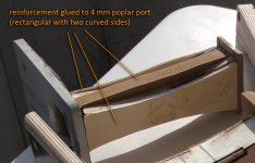
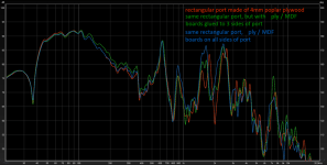
the resonance around 1,8 kHz (second harmonic of fundamental resonance) is getting stronger with stiffer (also heavier) port walls. the influence is not as strong as I thought when tapping on the port.
the first strong resonance at 650 Hz is the enclosure length resonance, around 900 Hz is first port resonance.
generally I would say: a non-resonant material and construction makes sense for the port. adding weight to the thin poplar plywood (thus making them more resonant) was counterproductive.
I suspect the difference of green graph between 100 and 500 Hz may just be a mic position inaccuracy.
here are my measurement regarding port wall reinforcement (stiffen them plus adding weigth). mic outside the port 10 cm to the side, 1V input swept sine.


the resonance around 1,8 kHz (second harmonic of fundamental resonance) is getting stronger with stiffer (also heavier) port walls. the influence is not as strong as I thought when tapping on the port.
the first strong resonance at 650 Hz is the enclosure length resonance, around 900 Hz is first port resonance.
generally I would say: a non-resonant material and construction makes sense for the port. adding weight to the thin poplar plywood (thus making them more resonant) was counterproductive.
I suspect the difference of green graph between 100 and 500 Hz may just be a mic position inaccuracy.
Last edited:
yes, that is possible.That could help break up the resonance.
Maybe just a few “bleed points” along the port surface.
the problem is to keep the efficiency of the port for the helmholtz resonator.
thus I tried to dampen resonances with as few port discontinuities as possible and putting them at the most effective location.
give me some hours (or days) and I will post my organized results!
I envy your industry. 🙂 Intuitively, always a risk, the flexible segment of the 'KEF' port would need to flex at the frequency to be suppressed. Any idea where it does?I tried this
It's not really clear to me what the whole discussion about the port walls is about ?generally I would say: a non-resonant material and construction makes sense for the port. adding weight to the thin poplar plywood (thus making them more resonant) was counterproductive.
A poor wall will just result in losses, since that is being transformed into energy to move the walls of the port.
Or another way of saying it, is that all ideal calculations/simulations are done with ports with ideal walls aka infinite amount of inertia = very heavy/stiff walls.
So a very thin flappy wall will just bring the Q-factor of the port down = less high impedance peak.
Which is not always easy to see from just the acoustic output from the port itself.
In general just a standard PVC tube thickness is often enough, the roughness of the tube is more significant.
So in theory it's beneficial to 3D print into the length of the tube, although that is not the easiest way to print.
If you want to go more stiff, you can go for aluminum pipes, they are cheap as well.
I guess, when we stretch the theory a bit more, this could have some effect on the harmonics as well.
Since they become less pronounced.
But I doubt that is a good thing. Or at least not the right way to solve the problem of these standing waves.
What you're saying about pressure waves and velocity waves is true. 🙂
When measuring so close-by they have a tendency to get bunched up.
That's one of the reasons why it can be tricky to measure a tube itself.
Not to talk about all kinds of additional artifacts higher up in frequency, which is a mix of pipe resonance and direct sound from the source itself. (I mean through the pipe, not because the speaker is close-by).
I personally would just only focus on the first resonance.
The goal here isn't to get rid of all resonances, but either move that first resonance out of the pass-band, or get rid/lower of it somehow.
Placing the BR port in a different location inside the cabinet can be beneficial as well here.
That 'noisy' behaviour is what occurs at the onset of turbulence and chuffing, which happens at a lower output level for the perforated port in my tests. For sure a bigger issue on my small cabinet with high xmax driver. The holes you show are HUGE compared to what I tested which was about 10x 1mm holes.My measurements were level calibrated and don't show that green behaviour:
https://www.diyaudio.com/community/threads/port-measurement.380629/post-6879909
Edit: check the impulse responses as well.
The perforations were simple ad hoc experiments using Home Depot drain liners, cut with a taper bit and filed clean internally, but the holes still had square edges so the limitations are recognized. The next step would be a printed port with tapered internal edges to minimize turbulence but I moved to sealed for now. That said I (casually) found the onset of turbulence using ~1 mm side wall ports to be quite high, approaching the driver's limits where it can be an arguable benefit to limit port flow and drive the enclosure towards sealed.
Could you make a comparison of equal wall thickness, but one as a layer damped approach? Maybe 6mm plywood vs 2x 3mm ply with a lossy adhesive between like no more nails or butyl tape?I wanted to keep this for later, but as the issue was raised now:
here are my measurement regarding port wall reinforcement (stiffen them plus adding weigth). mic outside the port 10 cm to the side, 1V input swept sine.
View attachment 1231293
View attachment 1231292
the resonance around 1,8 kHz (second harmonic of fundamental resonance) is getting stronger with stiffer (also heavier) port walls. the influence is not as strong as I thought when tapping on the port.
the first strong resonance at 650 Hz is the enclosure length resonance, around 900 Hz is first port resonance.
generally I would say: a non-resonant material and construction makes sense for the port. adding weight to the thin poplar plywood (thus making them more resonant) was counterproductive.
I suspect the difference of green graph between 100 and 500 Hz may just be a mic position inaccuracy.
If I made you fee l that way, I apologise. I do not mean to dismiss any well intentioned comment. I hope you will agree that sometimes ideal theory is not always demonstrated in the messy reality of experiments and the goals of the experimenter will determine the priorities of the experiment setup. It doesn't mean the experimenter is ignorant, only the goal is not aligned.You probably don't mean it that way, but that is how it very clearly comes across at least to me.
In that case, let's just bury to war axes? 🙂
We are technically talking about non-linear thermodynamics here, so yes, I am super aware of this.theory is not always demonstrated in the messy reality of experiments
Which makes this whole port/tube/pipe thing so tricky on itself.
But it's always good to use the theory as a fundamental foundation and a starting point to move from.
Or in simple words, what can we expect when we actually get our hands dirty.
Otherwise you run the risk of the trap of drawing the wrong conclusion because of oversight.
And trust me, I have bumped my head extremely often that way.
Or it because a journey of each to their own, which I think is just a mess that is not helpful to anyone.
Like I said in my previous post, when everything is done verbally (in written text), it becomes very difficult to understand what people are actually measuring and if that is even creating valid results.
I am not talking about scientific paper level validation, but just that you don't accidentally get the wrong things.
Which is very easy to do in acoustics and audio.
I personally always like to work from some sort of plan.
Come up with some clear idea first and test that "hypotheses".
Expand from there and make sure that the way I measure is repetitive but is also easy to copy by other people.
Always keeping an eye on the theory to test if what we are doing actually makes sense.
Not to sound rude or harsh, but I have seen plenty of "experiments" that are just invalid straight from the beginning.
Which is fine as a fun exercise or to spend time with your hobby, but unfortunately to many people draw real conclusions from it.
from my side it was just an experiment to check the influence of port wall resonances.It's not really clear to me what the whole discussion about th port walls is about ?
it was a quite non-scientific experiment that I wanted to do after knocking a port and hearing the resonance.
conclusion of my experiment was: the port walls have relatvely small influence at the major lower resonances and I followed another way to reduce those.
the difficulty with this subject is that (as many items in acoustics) ported loudspeakers are so full of compromises that it can get difficult to keep a good overview and evaluate all the parameters that usually also influence eachother.
I learned a lot doing these investigations until now but of course I am still no expert at all...
edit: apologies for my sloppy english after some glasses of wine 🙂
@stv
I was kinda confused about the max and min pressure modes.
But all of a sudden it hit me that I was thinking about a tube with two closed ends (aka a cabinet or a room).
They have the same harmonics and fundamental as function of their length.
Which makes it sometimes a bit confusing 😀
Easy trap to fall into sometimes.
These are pressure waves:
Last edited:
Most definitely!the difficulty with this subject is that (as many items in acoustics) ported loudspeakers are so full of compromises that it can get difficult to keep a good overview and evaluate all the parameters that usually also influence eachother.
Back in the day, they weren't so stupid after all with 3-way systems! 😉
Or also why a FAST system can also fix quite some problems!
The issue always is 2-way systems, or worse full-range system with just one speaker!
With a very super fancy word, those are called coincidence resonances.from my side it was just an experiment to check the influence of port wall resonances.
it was a quite non-scientific experiment that I wanted to do after knocking a port and hearing the resonance.
conclusion of my experiment was: the port walls have relatvely small influence at the major lower resonances and I followed another way to reduce those.
I only know them from like wall structures from buildings.
But they are a LOT higher than just the stuff we are interested in.
I think the port efficiency will go down first before that is gonna provide any problems.
Maybe only a problem when the pipe is super long and made out of a very stiff material like metal or glass?
I have my doubts that will be very significant though.
It's most definitely much lower than the pipe resonances themselves.
It's a bit of black magic, because there are so many variables involved. 😉 🙂I learned a lot doing these investigations until now but of course I am still no expert at all...
This also means that my theoretical tinker ideas from post 76 and 80 are gonna be slightly different as well;@stv
I was kinda confused about the max and min pressure modes.
But all of a sudden it hit me that I was thinking about a tube with two closed ends (aka a cabinet or a room).
They have the same harmonics and fundamental as function of their length.
Which makes it sometimes a bit confusing 😀
Easy trap to fall into sometimes.
These are pressure waves:
View attachment 1231384
https://www.diyaudio.com/community/...esonance-absorbers.388264/page-4#post-7445557
https://www.diyaudio.com/community/...esonance-absorbers.388264/page-4#post-7447982
Jeez, what an enormous brain fart 😀 😀
What I was thinking is instead of the air cushion in the helmholtz resonator, that a tunable panel might lend itself to damping across a wider frequency band.yes, that is possible.
the problem is to keep the efficiency of the port for the helmholtz resonator.
thus I tried to dampen resonances with as few port discontinuities as possible and putting them at the most effective location.
give me some hours (or days) and I will post my organized results
Helholtz devices create losses also, just an air spring.
Or better yet, just make a tapered port akin to a TL.
Last edited:
In theory the air in the port is considered as "weigth" and the enclosure volume inside is considered as "spring". Of course also the air in the port will be (slightly) compressed/expanded in reality.Helholtz devices create losses also, just an air spring.
Anyhow, not getting the most out of a helmholtz resonator defeats the purpose of such an enclosure, in my opinion.

A couple of posts have been deleted. You know who you are. Do not bring personal comments and attitude to the forum as this will result in bin time.
port variants in chamber 1
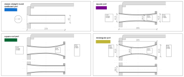
also refer to photo in post 104.in order to replicate and investigale the good results of curved wall rectangular port in chamber 2 (lower tuning) I tried different port shapes also for chamber 1. all ports except for the classic tube ports have the same (or very similar) cross section areas across the port lenght.
I removed the longitudinal enclosure resonance absorber (internal helmholtz absorber, see post 22) to better clarify the differences between port shapes.
here are the variant plans and the corresponding response curves, taken with 1 Vrms input, microphone 10 cm to the side from the center of the port.
due to the very different opening cross section shapes the mic distance from the port edge/roundover varied quite a lot, so i adjusted the responses for similar SPL in the useful bass region.
(chuffing noise and resonance results will come next!)
first the round cardboard tube port with exterior flange roundover and some different shape rectangular plywood ports:
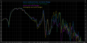
the most interesting detail is that the longitudinal port resonance at ~900 Hz of the classic round cardboard tube is non-existent.
this may be similar to the roozen paper, where the hard edge tube port had low Q resonance.
the enclosure longitudinal resonance however is the highest.
also, the rectangular port "picks up" most of the higher frequency enclosure resonances or produces them by itself.
as a general remark: the relation between enclosure volume and port size/ cross section would be very unusual for any bass reflex box, as this is the upper resonator of a 6th order parallel bandpass.
as far as I understand (and as can be seen below with small port) this results in very high resonance peaks. this would make a bass reflex box quite unusable.
next a very flat and wide port, the 3d-printed and smoothed round port and a very small cardboard tube port:


for better comparison i included the blue graph of the classic cardboard tube port.
my observations:
enclosure length resonance frequency varies.
the flat port seems to have no longitudinal port resonance at all (~900 Hz), but a very pronounced enclosure width resonance (1300 Hz, also 2nd harmonic of enclosure lenght). there also is a small resonance at around 350 Hz which i could not relate. maybe port structure resonance.
3d printed port is different: more port length resonance (900 Hz) but no enclosure width resonance.
i suspect the wide (side-to-side) opening of flat port picks up the width resonance pressure peaks.
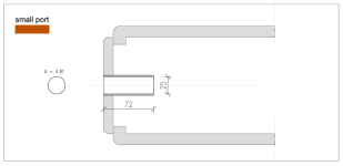
small port (2,5 cm diameter, length adjusted to same helmholtz resonance with hornresp) generally has much less resonances. the peak at 2,2 kHz is the port length resonance. other lower resonaces are enclosure length (650 Hz) and width/2nd harmonic lenght (1300 Hz) resonances.
while the small port seems to behave best in the response graph the chuffing is obviously worst (hard edges inside and outside).
I have no access to a 3d printer at the moment but I will definitely print an optimized shape port with similar size as the small cardboard port to test it.
edit, for clarification of plans:
dimensions in mm, cross section areas in cm² (for easier simulation in hornresp!)
Last edited:
chuffing measurement of straight classic round port
here is my chuffing measurement of straight round classic port without interior flange.
i used a sine with resonance frequency of chamber 1 (100 Hz) for maximum air speed in the port and took screen shots of the respective spectrum.
the spectrum of 1 V, 2 V, 4 V and 8 V are shown in shades of gray, background noise without signal is blue.
I also included the response graph in red for comparison.
on the left side are the THD+N percentages for the different input voltages.

as can be seen and as obvious, only the port resonances are being excited by the chuffing turbulences.
the longitudinal port resonance at ~900 Hz of the classic round cardboard tubeis non-existent.
the port resonance were masked by the other resonance peaks in the response graph but not at all "non-existent" as I wrongly stated above!
chuffing only starts above 2 V. the broad peaks in lighter grey are the 4 V and 8 V turbulence noises and port lenght resonance chuffing tone.
as I wrote in an earlier post, the port resonance peaks excited by chuffing are the most annoying and noticeable, because they are mostly not related to the input signal frequency (music), here the port lenght resonance is 750 Hz with no harmonic relation to 100 Hz. second harmonic at 1500 Hz, third at 2250 Hz.
the generally raised noise for the 4 V and 8 V signal between 50 and 4000 Hz is not very noticeable, but it does cost sound output energy, thus there is a slight compression effect of 0,4 dB between 1 V and 8 V.
also note that N in the 1 V and 2 V "THD+N" window is slightly higher because of background noise (traffic, wind and a suspicious refrigerator in my kitchen).
in my previous measurement for the chamber 2 port I found a good correlation for harmonic distorsion and chuffing noise, and in addition for the low bass frequencies the THD is usually quite high anyway, so I focused mostly on the "unmusical" chuffing resonance peaks in my further measurements.
Interesting that you say the resonance peaks excited by the chuffing are most audible and unpleasant to you. In my testing I felt there were two distinct 'noises' from chuffing: 1) Buzzing from the resonance peaks and harmonics. 2) Broadband 'fluttering wind' noise, generally heard in the higher frequencies where masking is lower.
Audio samples might be informative when talking about undesirable noise.
Here are the audio samples from my earlier graph showing turbulence from a port with 10 1mm holes at the centre position vs, a solid wall. I'd be interested to know other's impression, especially you STV, on if you hear what I've described and does it sound like your setup too? (sorry had to zip) Recommend listening on headphones, of course!!
Attachments
- Home
- Loudspeakers
- Multi-Way
- Investigating port resonance absorbers and port geometries
