stv!
'Ran across another paper here today . 'Thought you might be interested, if you haven't seen it already, and anyway might as well heap additional port stuff together for the next one searching.
Also found this image of an asymmetrical one by Kartesian.
'Ran across another paper here today . 'Thought you might be interested, if you haven't seen it already, and anyway might as well heap additional port stuff together for the next one searching.
Also found this image of an asymmetrical one by Kartesian.
Attachments


Thank you very much @Hearinspace , I did not know this paper. It's an great summing up of actual state of research!
I am stuck to the bed with some kind of flu - further investigations just wait to be published.
I am stuck to the bed with some kind of flu - further investigations just wait to be published.
I am stuck to the bed with some kind of flu - further investigations just wait to be published
Ahh, enforced downtime. Quiet time to ponder ones position and trajectory in the universe . Use it well! Once you're up and around, your friends , family and work obligations will have you back running like a mad chicken. In other words, Wishing you well ! : )
I've had this in the idea pile for some time. It's for a small 2way BR that I'm currently working on, and its similar in concept to what @b_force posted earlier. There are a lot of resonances that can occur when you stick a pipe in a box. Trying to damp them away usually kills the BR response.
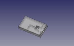
The idea (see attached pic) : the main port (red) is sized to tune the box to the desired freq (used Hornresp). The main port connection to the woofer chamber is via a hole at the top (light blue). Then a short closed stub is added (purple) to reduce port pipe resonance, then an "open" stub (green) with a damped chamber (green) is added to reduce other woofer chamber resonances. This stub tuning arrangement (acoustic filter?) could be built as an internal layer, or plumbed in pipes (maybe, distances are critical), The original port tuning notch does not move, indicating the additional stubs did not change the alignment.
P.S. Best wishes @stv for a speedy recovery
Looks pretty neat.
So the grey enclosed space could be a continuation of the main enclosure?
What sort of volume is the total of port and stubs?
So the grey enclosed space could be a continuation of the main enclosure?
What sort of volume is the total of port and stubs?
The outer grey walls are the cabinet walls. The stub structure is a "layer" (net 5cm thick) in the woofer chamber (25L). The green chamber is 1L.
This is basically just a helmholtz resonantor. Dampening that chamber will really help btw.The idea (see attached pic) : the main port (red) is sized to tune the box to the desired freq (used Hornresp). The main port connection to the woofer chamber is via a hole at the top (light blue). Then a short closed stub is added (purple) to reduce port pipe resonance, then an "open" stub (green) with a damped chamber (green) is added to reduce other woofer chamber resonances. This stub tuning arrangement (acoustic filter?) could be built as an internal layer, or plumbed in pipes (maybe, distances are critical), The original port tuning notch does not move, indicating the additional stubs did not change the alignment.
Although I find it a little hard to see what's going on.
Also construction wise it's very tricky to do.
I ordered myself some parts, hopefully they will be here next week so I can do some experiments as wel 🙂
^^ The chamber is damped 🙂 It should be straight forward to build. It's just some internal walls and another layer to seal it.
I see a lot of corners and such.^^ The chamber is damped 🙂 It should be straight forward to build. It's just some internal walls and another layer to seal it.
Easy with a CNC, not so much by hand.
Btw, do you have a full 3D drawing, I am still having trouble picturing it inside a speaker cabinet?
^^ The front baffle (port exit) is 25mm thick, the walls are 12.7mm thick. No CNC, just pieces of 12.7mm thick plywood (50mm high) glued into the pattern shown in the slice layer. I've removed the top and bottom panels of the slice to make it easy to see in. My cabinet cross section has this exterior outline.
That's an awful lot of small tiny cuts than?glued into the pattern shown in the slice layer.
this is interesting!Then a short closed stub is added (purple) to reduce port pipe resonance, then an "open" stub (green) with a damped chamber (green) is added to reduce other woofer chamber resonances.
when I tried something similar with my rudimentary calculations all I got was a new resonance of interacting port lenght and helmholtz-resonator intended to remove port resonance (see post 58).
I suppose simulation is the only viable approach here!
Best wishes @stv for a speedy recovery
thank you!
Last edited:
Have I labeled this correctly? If so, it appears the taps, at least the purple one, are not at the center of the port? What resonances did each of the taps work to lessen? When you say the green is for the woofer box, you mean this dampens the typical standing waves in the box? Not so much about resonances of the port itself?

this is interesting!
when I tried something similar with my rudimentary calculations all I got was a new resonance of interacting port lenght and helmholtz-resonator intended to remove port resonance (see post 58).
I suppose simulation is the only viable approach here!
@stv I read that post again, and all I can suggest, based on the sim I did, is that both the stub dimensions, and chamber volume are important otherwise the noise moves to a new location. The secondary chamber (green) volume is also relative to the main chamber volume.
@augerpro That's the correct interpretation of the drawing. My originally attempts, had stubs at the reflex port length center, then I found I could move the placement, length and the cross section and get similar results. So I made it easier to build. The major improvement is in "other" resonances, but I needed both stubs to prevent just moving the noise. The actual port resonance should be spikes at (c/2L) at even harmonics but there seems to be more noise than that. I suspect there is a more complicated system interaction. The stubs and chamber were trial-error attempts in LEM (easiest) and I'll repeat in BEM to verify and then again in the prototype. I was trying to minimize the total port "noise" . I thought it was an interesting result,
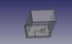
I've tried to increase the transparency of the drawing to better show the intended assembly. The bottom cover would be removable to make adjustments if required.
Attachments
Just came across a klippel document referring to this effect under 3.1.6 (see fig 13):outwards: directed flow
inwards: undirected flow
https://www.klippel.de/fileadmin/_m...linearities–Causes_Parameters_Symptoms_01.pdf
In that case, something similar would also work with just PVC pipes.
I think that is a lot easier to implement than having to saw all those specific pieces.
It's also a lot less waste of space.
That purple part is technically not needed to make the helmholz absorber (green) effective.
I think that is a lot easier to implement than having to saw all those specific pieces.
It's also a lot less waste of space.
That purple part is technically not needed to make the helmholz absorber (green) effective.
yeah, in addition, you would also like to make both ends of the port symmetrical, otherwise there will be a asymmetrical load on the loudspeaker.Just came across a klippel document referring to this effect under 3.1.6 (see fig 13):
https://www.klippel.de/fileadmin/_m...linearities–Causes_Parameters_Symptoms_01.pdf
Correct!
I addition, as I tried to show with my "port stall" theory you want to achieve symmetrical airflow for either side in the first place to avoid turbulences that create chuffing noises and compression effects (in other words wasting precious sound energy in turbulent airflow).
I addition, as I tried to show with my "port stall" theory you want to achieve symmetrical airflow for either side in the first place to avoid turbulences that create chuffing noises and compression effects (in other words wasting precious sound energy in turbulent airflow).
- Home
- Loudspeakers
- Multi-Way
- Investigating port resonance absorbers and port geometries