I just managed to get my first iteration-optimisation spreadsheet to work.
It's not the cleanest calculation method, but it gets the job done - I guess this is the beauty of iterative processes: it may take a few more steps, but it will finally arrive to a reasonable result (EDIT: for reasonable inputs, that is!).
I'll clean up the file and add the graphic output and then I will finally post it!
I apologise for the delays!
Last edited:
Yeah. I think most SLA/resin 3D printers could handle this level of detail without breaking a sweat, but the end product could suffer from warping/shrinking, no idea if it'd be enough to significantly effect tuning. And of course their is the toxicity dangers of resin prints that need to be delt with.Great!! I absolutely love the look!
Now we just have to find a 3d-printer that manages to not let them disappear in filament slices...
detail comparison:
Though with 0.2mm FDM nozzles golf-ball dimples are probably not impossible, getting a smooth production-like finish might not be reasonable, since any filler added is just going to fill in the dimples and no one wants to hand sand 100s of individual 2mm-wide dimples.
What we all really need is few giant chunks of solid aluminum and a 7-axis CNC (all for free, of course).
The exact tuning of ported enclosures is greatly overrated, in my opinion. Simulators (and also my excel tool) suggest absolute accuracy and the ability to tune for perfectly straight response down to the tuning frequency. But what's the point if a room, the speaker and listener positions change the response completely?no idea if it'd be enough to significantly effect tuning
In addition, many designers take data sheet TSP and the real driver might be far off ...
And once you turn up the volume the parameters change again ...
Even weather change will influence tuning.
I also understand now why sharp tuning peaks of high qts drivers are best avoided even if the simulated response looks fine.
So I agree, sla print would be perfect for such a port!
I plotted a graph of seven representative ports and tried to find a formula to approximate this graph:Rule N°2: The minimum allowed STROUHAL number is related to the port lenght/port exit diameter ratio.
again simplified:
a long port is less disturbed by eddy flow disturbance at the port entrance/exit. This can be measured by looking at the compression behaviour of the port.
long ports with a length/exit diameter ratio of 4 or more allow a STROUHAL number of ~0.5 or even less
short ports with a lenth/exit diameter ratio of 2,5 or less only allow STROUHAL numbers of 1 or even more
the correlation is not linear and even shorter ports will behave much worse (thus needing much more surface to be non-compressing).
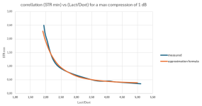
The approximation formula is:
STRmin = 8/(((Lact/Dext)-0,4)^3,5)+0,35
This is a rough first estimation and included in my first optimizer spreadsheet to be published next.
Thus, usual optimizer results will be ports significantly longer than the (exterior) diameter, except maybe for very big enclosures with low maximum required SPL which is rarely the case.
This (of course) corresponds to my finding that longer ports are less prone to turbulent flow/flow disruption and resulting tuning change with apparent compression.
Edit:
Lact = actual port length
Dext = port opening diameter, without considering roundover
STRmin = minimum allowed strouhal number to stay below 1 dB of compression
Last edited:
Yeah. I think most SLA/resin 3D printers could handle this level of detail without breaking a sweat, but the end product could suffer from warping/shrinking, no idea if it'd be enough to significantly effect tuning. And of course their is the toxicity dangers of resin prints that need to be delt with.
Though with 0.2mm FDM nozzles golf-ball dimples are probably not impossible, getting a smooth production-like finish might not be reasonable, since any filler added is just going to fill in the dimples and no one wants to hand sand 100s of individual 2mm-wide dimples.
What we all really need is few giant chunks of solid aluminum and a 7-axis CNC (all for free, of course).
I have a resin / SLA printer. There is not a toxicity danger to humans unless you drink it. There is a possibility of developing a sensitivity if you handle the uncured liquid without gloves or work in a manufacturing setting without proper ventilation. The reddit stories as best as anyone can tell are made up and / or the person admits to other chemical exposure which more likely explains their story. Just as we come here, AVSForums, and AudioScienceReview because r/diysound and r/diyaudio are cesspools of crackpots; SLA / resin printing is trapped in reddit BS purgatory until a group of people who know what is going on spin up independent forums.
It's incredibly easy to varnish or paint resin prints and rattle can paint is a bigger respiratory hazard than resin, so that is the ultimate end of story even for those who don't understand most resin prints are effectively acrylic. As for shrinkage, that is handled via a feedback loop of printing test pieces and dialing the shrinkage back in. Still a factor, but usually shrinkage has known ways to mitigate it well. Warping is similarly handled by designing and orienting the prints correctly.
Here's a bass port printed from STV's previous sheets and FreeCAD model in resin (it works great on my Seas Loki IV).
For resin printing and audio though, I am more interested in printing difficult waveguides within the size constraints of my printers and various Helmholtz and quarter wave resonators / absorbers similar to Kef's Meta pucks.
If you or @stv have a semi-final design or two you want printed in resin for PoC, DM me to exchange contact info since I don't check in here for weeks at a time sometimes. I'd print stuff for free* which will fit on either of my printers (Saturn 4 Ultra, Mono M3 Max) to make my contribution towards these efforts as long as you guys cover shipping.
*If the resin consumption volume is somehow extreme or multiple part iterations are required, we might need to discuss materials cost. For point of reference, the bass port above is <$3 in resin, so I have my doubts on even a larger compound set of parts breaking $5-10. But the real work is orienting / formatting the part and adding supports which I'm offering.
Last edited:
I recently came across this interesting port flare design from Yamaha called "Twisted Flare Port", some of the products it's used in is their subwoofer KS-SW100, MSP3A monitor, and also some of their piano keyboards with built in speakers have it.


Don't know how much this design can reduce port resonances, appears to be focused on addressing the turbulence occurring around the port entry/exit.
https://audioxpress.com/news/yamaha...ed-reference-monitors-with-twisted-flare-port
Don't know how much this design can reduce port resonances, appears to be focused on addressing the turbulence occurring around the port entry/exit.
https://audioxpress.com/news/yamaha...ed-reference-monitors-with-twisted-flare-port
PORT GEOMETRY OPTIMIZER TOOL
Here it is finally - my first optimized port geometry calculator tool.
Same as my previous tools, the spreadsheet is protected to avoid accidental mistakes, but there is no password - so feel free to unlock and modify!
For simplicity the enclosure volume input is limited to metric, but the corresponding cubic feet volume is calculated and all result parameters are also provided in inches.
The file includes two sheets, one for the input/output and one for iterations/calculations.
Calculation principles:
Required inputs are only tuning frequency, net enclosure volume and max. desired port output SPL (4pi/1m).The maximum required port air volume displacement is then calculated from the tuning frequency and max SPL using the calculation method provided here.
Keep in mind that the port output SPL might and usually will be (slightly) lower than the total system output.
From the max air displacement a first minimum port exit diameter value is calculated, using a (rather high) minimum STROUHAL number of 3.
The starting value port length is then calculated for a straight port via the salvatti/devantier/button tuning formula.
Iteration process:
The first iteration steps 1-10 just gradually increase the flaring of the port, up to the ideal Dext/Dmin ratio of 1.5 (see post #812)From step 11 to 20 the port is very roughly adjusted (usually reduced) to the minimum allowed STROUHAL number, depending on the Lact/Dext ratio (see post #844, just above).
From iteration step 21 to 350 the tuning calculation is done in decreasing modification steps using the salvatti et al formula with correction factor based on @augerpro's and my actually built speakers (post #747).
The iteration steps are required, because the tuning frequency and min allowed strouhal number calculations affect eachother and only approach an ideal result stepwise.
After 350 iteration steps any sensible input will lead to a useful result.
There are some input values that will NOT provide a result. This is usually the case for very big enclosure volumes with low required output SPL or high tuning frequencies that would only require a very short (or negative lenght!) port. I will try to solve this issue, but I guess for all useful cases the existing tool will provide a solution.
The development of the iteration process can be observed on the "iterations+details+grafic" spreadsheet, there is a graph showing the port length vs. iteration steps.
It would be possible to include even more iteration steps, but in my opinion it does not make much sense. Tuning of a ported speaker depends on so many uncontrollable or high-tolerance parameters, that any accuracy below ~5% is only useful for the designer's OCD.
Output:
The port geometry result is provided via the following parameters:- actual port lenght
- exit diameter
- minimum diameter
- roundover radius
These parameters already fully define a round, circular flare port.
In addition the calculator provides:
- NFR
- port flare curvature radius
these parameters may be helpful for the use of parametric 3d models provided in this thread.
I also added a very rudimentary graphic representation of the port geometry, see "port visualization graph".
This graph is (for now) very limited to the excel strandards, so it only provides dimensions in % of port length, because I did not find any other solution for an adapting scale graph that still keeps X and Y axis scaled equally.
If this graph shrinks to only a point on the left end the iteration process failed and you might have to adjust the inputs.
I tested the tool using several examples, but please be aware that it's still a BETA version, to be tested and verified.
Any comments are welcome!
Attachments
Last edited:
Very interesting, thank you!Don't know how much this design can reduce port resonances, appears to be focused on addressing the turbulence occurring around the port entry/exit.
The turbulence at port exit and entry do excite the first longitudinal resonance of the port, see my RTA graphs here for example!
Amazing! Going to get one of these ports in an enclosure ASAP. Will report the results here
@stv how satisfied are you that Dext/Dmin = 1.5 is the optimal value? Was this based on compression and distortion/chuffing? I seem to remember it was but my work laptop won't let me see your pics right now.
I really want to give you a big thanks for taking this project to fruition. The community will get huge value out of this, probably even after you're long gone! Great work!
I really want to give you a big thanks for taking this project to fruition. The community will get huge value out of this, probably even after you're long gone! Great work!
I found this "ideal" value by studying the set in of compression.@stv how satisfied are you that Dext/Dmin = 1.5 is the optimal value? Was this based on compression and distortion/chuffing?
In the compression vs. STROUHAL number and compression vx. MID PORT STROUHAL number I found that ports with Dext/Dmin ratios of above 1.5 seem to be limited by the central section of the port (Dmin) and ports with Dext/Dmin ratios of lower than 1.5 are limited by Dext. This conclusion was possible by comparing the STR/compression and MPSN/compression curves. See this section of post #812 and the previous one.
For an even more refined optimization of Dext/Dmin ratio some more testing would be necessary. It seems that for short ports the ratio could be slightly higher. But the optimized ports will usually not be very short, to allow a better laminar flow and a lower allowed strouhal number.
I realized that I did not mention that the min allowed STR value calculation is based on a maximum allowed compression of 1 dB.
I found previously that chuffing (and also distortion) is very much correlated to compression. See Post #621, post #656, or post #680 (the latter with description of audibility of chuffing, note the chuffing of the straight tube is created by the very sharp tube edges).
With a compression value of 1 dB both chuffing and distortion for flared ports are very low (chuffing inaudible from hearing distance and H3 usually below 1%).
By the way, in my opinion the port harmonic distortion is generally overrated. In the bass range the driver will produce more distortion than a port (as long as the flow stays laminar).
Example from Eirin's Audio Corner, Yamaha NS-800A:
Impedance and distortion at 86 and 96 dB/1m:
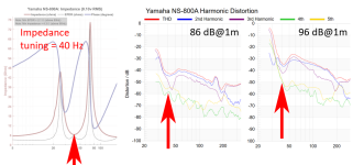
All relevant distortion graphs have a local minimum around helmholtz tuning.
But of course this port has an optimized shape (twisted flare!) and is mounted on the rear of the speaker.
Thank you very much, I very much appreciate this - it has been a very fruitful collaboration!I really want to give you a big thanks for taking this project to fruition. The community will get huge value out of this, probably even after you're long gone!
... though I am not planning to disappear very soon! 😊
Last edited:
Thank you for mentioning this 🙂By the way, in my opinion the port harmonic distortion is generally overrated. In the bass range the driver will produce more distortion than a port (as long as the flow stays laminar).
What about IMD?
Hi stv and thanks for sharing the new spreadsheet! Making some test runs with it, seems to work as intended 🙂
However I'm running into practical issues with it, as it gives optimal ports that are way too big to be practical for box that I had in mind. It's nice to have optimal but if its tough to implement due to other constrains for a project then next best would be to have as good as possible port performance, that still fits.
I'm thinking two slap-ons that could help manage with practical issue of size:
1. add either port diameter or port length as input as well to constrain the port size. What's the trade-off, max SPL drops, or compression is allowed to increase?
2. what if I just scaled down the original (what the spreadsheet currently gives) until both the length and Dext are manageable, which ever was too big. it would be nice to see how much it lacks from the target (SPL?), or how much compression increased at the original target SPL.
I did not look into modifying the spreadsheet yet, just asking these quickly here if you have any insight to these. Sorry if silly, I'm very tired atm.
Oh, and another, I need to use two ports, how big of an adjustment would that be for the optimizing spreadsheet?
Thanks!
tmuikku> I would lower the SPL target and then allow the spreadsheet to optimize. You should still end up with a better port than the equivalent length straight port (probably implying that if you optimized around Strouhal number a straight port would be much bigger than you'd like too).
I guess that's because of high desired SPL inputs.that are way too big to be practical
I also guess for PA use much higher compression and chuffing levels will be acceptable. I suppose we could make another optimizer spreadsheet using higher compression and chuffing limits and get smaller ports.
You could also just input a lower max SPL (-5 dB maybe?) and use the corresponding port, accepting some compression and eventual chuffing.
Keep in mind that longer ports (length much more than 2*Dext) have a rather benign laminar flow disruption behaviour.
I also wouldn't be too surprised if (and I wrote that before) usual ports are simply mostly too small for high SPL peaks and the bad reputation of ported speakers comes from this.
And finally you can always use the flared port tuning calculator to find a correctly tuned port, without all the max SPL calculation.
Edit: @augerpro was quicker!
By the way what are your input values?
Just use half the enclosure volume and -6 dB max SPL, but the correct tuning frequency and you get the dimensions for one of two ports.Oh, and another, I need to use two ports, how big of an adjustment would that be for the optimizing spreadsheet?
EDIT: let me check this once more ... I'll confirm as soon as possible!
EDIT 2: now that's interesting - I didn't think of that:
Splitting the port into two makes the Lact/Dext ratio for the single port bigger, allowing for a smaller STROUHAL number ad thus, reducing the total port dimensions. So while splitting the port up into more smaller ones increases the potential losses and turbulent boundary layer flow, it also reduces the total port volume. I'll have to think more about this!
Last edited:
Augerpro, stv, thanks!
Yeah I can drop SPL to get into suitable shape. What concerns me is I need to drop it +10db!😀 so, trying to figure out whether calculations are correct, and when they are then estimate if my plan is too much of a compromise so need to determine if I have to change the plan.
I'm checking in VituixCAD enclosure tool and there the box should be able to reach 120db ~35Hz, with two 30cm long 16cm diameter ports with what looks somewhat reasonable port velocity.
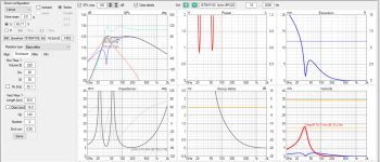
If I cut enclosure volume in half to use only one port with same dimensions for same tuning, it's about 114db output at 35Hz as stv suggested. This however, gives much higher air velocity in the port, which would make the optimizer to figure out bigger port. Thus I think this is not optimal way to find the port shape for a box with two ports.
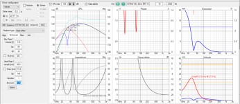
If I pluck 110 liters, 35Hz and 114db into the optimizer I get much larger port than in VituixCAD:
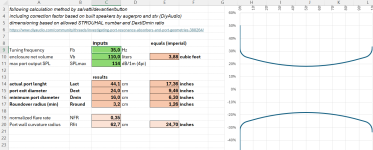
I can get optimized port to similar dimensions as VCAD sim if I drop SPL to ~102db.
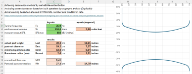
Well, this port would be good to ~108db as two ports per bigger box. This is still 10db below my target output and I'd like to estimate what it actually means, how much would compression increase past this, and so on. I can of course build it and measure things to be sure, but such a big optimal port requires different cabinet geometry so my plan would change dramatically.
Where is the 1db compression defined for the optimizer? I could perhaps tweak that to figure out what's the compromise.
Yeah I can drop SPL to get into suitable shape. What concerns me is I need to drop it +10db!😀 so, trying to figure out whether calculations are correct, and when they are then estimate if my plan is too much of a compromise so need to determine if I have to change the plan.
I'm checking in VituixCAD enclosure tool and there the box should be able to reach 120db ~35Hz, with two 30cm long 16cm diameter ports with what looks somewhat reasonable port velocity.

If I cut enclosure volume in half to use only one port with same dimensions for same tuning, it's about 114db output at 35Hz as stv suggested. This however, gives much higher air velocity in the port, which would make the optimizer to figure out bigger port. Thus I think this is not optimal way to find the port shape for a box with two ports.

If I pluck 110 liters, 35Hz and 114db into the optimizer I get much larger port than in VituixCAD:

I can get optimized port to similar dimensions as VCAD sim if I drop SPL to ~102db.

Well, this port would be good to ~108db as two ports per bigger box. This is still 10db below my target output and I'd like to estimate what it actually means, how much would compression increase past this, and so on. I can of course build it and measure things to be sure, but such a big optimal port requires different cabinet geometry so my plan would change dramatically.
Where is the 1db compression defined for the optimizer? I could perhaps tweak that to figure out what's the compromise.
Last edited:
- Home
- Loudspeakers
- Multi-Way
- Investigating port resonance absorbers and port geometries