I am planning on my first tube amp build, I have decided on a Tubelab SSE and the chassis design I am working on has the power and audio transformers inverted (upside down). They would be separated from the tubes/other electrics by sheet metal.
I know tube amps, especially SE are very picky about the transformer location/orientation. Can anyone tell me the implications of inverting the transformers?
I know tube amps, especially SE are very picky about the transformer location/orientation. Can anyone tell me the implications of inverting the transformers?
I am planning on my first tube amp build, I have decided on a Tubelab SSE and the chassis design I am working on has the power and audio transformers inverted (upside down). They would be separated from the tubes/other electrics by sheet metal.
I know tube amps, especially SE are very picky about the transformer location/orientation. Can anyone tell me the implications of inverting the transformers?
If "inverted" you mean hanging upside down attached to the sheet metal, there is no difference in performance, and you may gain some additional isolation from the electronic if the sheet metal is grounded.
However, the main thing to keep in mind is the orientation of the power supply transformer core in relation to the output transformers. Make sure they're at 90 degrees relative to each other to minimize hum.
If you're mounting the transformers inside the case, separated by sheet metal, and the electronics on top, then the added lead length can also pickup stray magnetic interference.
Regardless of mounting position, keep AC separate from audio signals and the transformer cores (unless they are potted, shielded, and grounded) at 90 degrees from each other.
Thanks for the knowledge and confirmation, happy my plan should work. I will try and keep the leads as short as possible.
If it comes down to a choice between keeping the OPTs away from the Power T or short leads, I'd go for keeping the trannies apart and slightly longer leads. As well, if you use a filter choke in the PS try to keep it well clear of the PT.
S.
S.
It’s just a drawing at the moment but in theory the leads could be very short, that’s sorta how I started down this rabbit hole to begin with. If it’s helpful I believe I have enough room to run the choke and/or PS cap on the electronics side (this could provide aesthetic advantages as well)
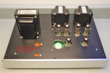
The SPP shown in the link above and the attached picture has tube sockets and higher wattage resistors on the top side of the board, low watt res. and caps on the bottom side. The board is spaced from the top plate with 6-32 x 3/4" long spacers from Mouser. The power trannie voltage was a bit on the high side for EL84s so I mounted the rect. tube off-board and added another cap and the choke before running B+ to the board.
A later version used trannies that don't require large cut-outs and the rect. tube is on the board. (See pic.)
The hum, though not very high, was reduced considerably when the choke was added. More through good luck than good planning this is a very quiet amp, noise-wise.
S.
A later version used trannies that don't require large cut-outs and the rect. tube is on the board. (See pic.)
The hum, though not very high, was reduced considerably when the choke was added. More through good luck than good planning this is a very quiet amp, noise-wise.
S.
Attachments
The SPP looks great, very clean with the choke under the chassis and demonstrates the concept I am going for...talking and seeing other people’s work is inspiring, you’ve got me searching and ordering parts!
You brought up something else of interest, I had considered the possibility of running the rec tube and preamp tube off board (mostly for aesthetics to be honest) but my assumptions were this a has some chance of adding noise and a good chance of adding complication, is that it pretty much the case?
You brought up something else of interest, I had considered the possibility of running the rec tube and preamp tube off board (mostly for aesthetics to be honest) but my assumptions were this a has some chance of adding noise and a good chance of adding complication, is that it pretty much the case?
I think it makes sense, from the point of view of heat dissipation and/or loading, to mount the rect. tube off-board. I think it best to keep the 9-pin tube (tubes?) on the board for short signal runs.
S.
S.
If you have a choice, keep the choke farther from the output transformers than from the power transformer.
Also, orient the choke coil at 90 degrees to the output transformer coils.
Use aluminum chassis, steel chassis conducts magnetic fields from both power transformer and choke, to the output transformers.
Fortunately, push pull transformer laminations (interleaved E's and I's) are less sensitive to magnetic fields, versus single ended transformers that have an air gap, with all E's on one side, and all I's on the other side of the air gap.
Last edited:
- Home
- Amplifiers
- Tubes / Valves
- Inverting Transformers Tubelab SSE