Hi Piersma,
I am really enjoying my Circlotron amplifier. Something about the sound is quite musical and non-fatiguing.
No adjustments were necessary or even possible - this is different than most of my other amplifiers. Bias was about 205ma and DC offset was only 3mV.
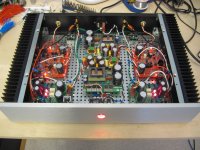
Attached is a picture of my build. Configuration is dual-mono in a Modushop 2U chassis. Power is supplied two Connex SMPS300RE +/-36V power supplies that had been sitting on my shelf for about two years due to disappointing results when tested with a class AB amplifier (sound was rather lifeless and flat). Using a capacitance multiplier to cleanup any SMPS noise, add more per-rail capacitance, and improve transient response seems to have made a huge difference. I had planned to eventually replace the SMPS power supplies with a simple linear power supply but may now stay with the current configuration.
The only surprise was quite a loud turn-on pop. This can be easily fixed by adding DC speaker protection with a small power-on delay. Until then, I am using an external speaker selector switch box to temporarily disconnect my speakers.
Thank you for making your PCBs available to the diyaudio community and for your support.
I am really enjoying my Circlotron amplifier. Something about the sound is quite musical and non-fatiguing.
No adjustments were necessary or even possible - this is different than most of my other amplifiers. Bias was about 205ma and DC offset was only 3mV.
Attached is a picture of my build. Configuration is dual-mono in a Modushop 2U chassis. Power is supplied two Connex SMPS300RE +/-36V power supplies that had been sitting on my shelf for about two years due to disappointing results when tested with a class AB amplifier (sound was rather lifeless and flat). Using a capacitance multiplier to cleanup any SMPS noise, add more per-rail capacitance, and improve transient response seems to have made a huge difference. I had planned to eventually replace the SMPS power supplies with a simple linear power supply but may now stay with the current configuration.
The only surprise was quite a loud turn-on pop. This can be easily fixed by adding DC speaker protection with a small power-on delay. Until then, I am using an external speaker selector switch box to temporarily disconnect my speakers.
Thank you for making your PCBs available to the diyaudio community and for your support.
Attachments
hi Pronk,
Glad you like the Inverted J-FET Circlophone!
The non-fatiquing character of this amplifier must be attributed to the non- switching output of this configuration.
Your setup looks pretty neat! Enjoy!
Glad you like the Inverted J-FET Circlophone!
The non-fatiquing character of this amplifier must be attributed to the non- switching output of this configuration.
Your setup looks pretty neat! Enjoy!
Hi Sjerko,
After all this time I finally got around to test both J-Fet Circlophone channels.
The addition of the (optional) 5.6 ohm resistor next to the output pin got rid of the oscillation I was experiencing.
Everything works fine now even with faster MJL4302 outputs.
Thanks again.
Jacques
After all this time I finally got around to test both J-Fet Circlophone channels.
The addition of the (optional) 5.6 ohm resistor next to the output pin got rid of the oscillation I was experiencing.
Everything works fine now even with faster MJL4302 outputs.
Thanks again.
Jacques
High Ft devices O.P.S.
hi Jaqcues,
Good to hear you got rid of the modest oscillations you experienced with the high Ft (10MHz) MLJ-4302. The Zobel is network is not strictly needed and that why it is optional with the MJL21193 with an Ft of 4MHz.
Can you confirm the sound-qualities (SQ) Pronk experienced?
Enjoy your build!
best regards,
Piersma
Hi Sjerko,
It works great so far but I did not try it at its best yet (still powered from a modest lab power supply).
A classic linear toroid psu 2x42Vdc with 2x20000uf is planned.
Cheers,
Jacques
It works great so far but I did not try it at its best yet (still powered from a modest lab power supply).
A classic linear toroid psu 2x42Vdc with 2x20000uf is planned.
Cheers,
Jacques
Hi guys,
I ran into these Circlophone threads and I'm afraid there is a Circlophone in my future.
In learning about the architecture, I found that Schiit Audio is selling 2 amps that use "circlotron-style topology". Their Ragnarok amp has been very well reviewed. It's nice to see old ideas being reborn and made better. Even better, doing it DIY style.
Nice.
hi Alchamist,
With reference to schematic in post #1, you do not need to change any component values for a 42V supply voltage. For Q5/Q6, only BC560A !
With reference to schematic in post #1, you do not need to change any component values for a 42V supply voltage. For Q5/Q6, only BC560A !
I've some doubt about Idss classification of input FETs (2SK170).... I need help to make the right choice.
GR=2.6~6.5 mA
BL=6.0~14.0 mA
Thank you
GR=2.6~6.5 mA
BL=6.0~14.0 mA
Thank you
JFET
hi Bsurfer,
You could use both GR and BL, preferred type would be the BL.
Have fun building !
hi Bsurfer,
You could use both GR and BL, preferred type would be the BL.
Have fun building !
Hello,
I get lots of components but some user has trouble with practice. Could you share last version of circuit?
I get lots of components but some user has trouble with practice. Could you share last version of circuit?
So don't know if this thread is dead or not?? Anyway Piersma I have built your earlier version on the green boards years back. You sent me a handful of red boards that I havent used yet. So it is a little confusing between the different versions. Can I just build the amp and go by the values that are silkscreened on the board? Using the MJL21193 outputs what is the max power I can operate at? I'm assuming +/-50v rails. What is the function of the Q4/Q5 in the schematic? Current source? If I want to operate single ended what input terminals do I use? Anyway good to talk with you again, thanks
@Freecrowder
I have to digup the files and come back to you.
I would not go beyond 50 Volts supply-voltage, although the MJLs have margin left.
I have to digup the files and come back to you.
I would not go beyond 50 Volts supply-voltage, although the MJLs have margin left.
- Home
- Amplifiers
- Solid State
- Inverted J-FET Circlophone Builders thread