I had a cap inverted which caused a little grief but fortunately I discovered it before it smoked up the lab. Anyway I got that replaced and the amp fires up but there appears to be some oscillation. The only things I have different from the schematic is I have 1p in C7 instead of 1p5 because I didn't have any. I also have an elco cap in C3 for the same reason. Both are on order. I may try to build a 1p5 cap out of some others but do you think this 1p cap is enough to cause oscillation?
Thanks, Terry
Thanks, Terry
Attachments

Oscillations
hi Terry,
Did you use 10 Ohms degeneration resistors for R36 and R37?
Place the resistor of the Zobel network R38: 5.6 Ohms.
The 1pF feedback cap should not cause you any troubles.
hi Terry,
Did you use 10 Ohms degeneration resistors for R36 and R37?
Place the resistor of the Zobel network R38: 5.6 Ohms.
The 1pF feedback cap should not cause you any troubles.
Hi Jacques,
One remark: Terry did use the recommended MJL21193 output transistor, in your setup you used the higher Ft MJL type. Small oscillations tendencies might appear with higher Ft transistors.
One remark: Terry did use the recommended MJL21193 output transistor, in your setup you used the higher Ft MJL type. Small oscillations tendencies might appear with higher Ft transistors.
Hi Piersma,hi Terry,
Did you use 10 Ohms degeneration resistors for R36 and R37?
Place the resistor of the Zobel network R38: 5.6 Ohms.
The 1pF feedback cap should not cause you any troubles.
I remembered a couple other things that I changed. I used 4R7 for R38. I didn't have 5R6. I also used MJE15032 for the drivers. I did use MJL21193 for the outputs. Everything else is per the silk you sent me. When I get a chance I will post a scope shot of what I see.
Oscillations
hi Terry,
When I look at the picture you posted, I don't see R38 mounted.
4R7 (instead of 5R6) is a perfectly fine for the Zobel network.
Please confirm the value of R36 and R37. (degen. resistors LPT)
hi Terry,
When I look at the picture you posted, I don't see R38 mounted.
4R7 (instead of 5R6) is a perfectly fine for the Zobel network.
Please confirm the value of R36 and R37. (degen. resistors LPT)
hi Terry,
When I look at the picture you posted, I don't see R38 mounted.
4R7 (instead of 5R6) is a perfectly fine for the Zobel network.
Please confirm the value of R36 and R37. (degen. resistors LPT)
I did not mount R38. It said optional so I left it off. I can install it though I will have to make on since I don't have 5R6 2W in my bin. For R36/37 I installed 12R. I can change those to 10R if you think it will help.
hi Terry,
R38 is non-critical, you could use any resistor between 4R7 and 8R2. (2W)
Leave resistors R36 and R37 12 Ohms.
R38 is non-critical, you could use any resistor between 4R7 and 8R2. (2W)
Leave resistors R36 and R37 12 Ohms.
Hi Piersma,
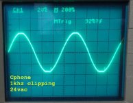
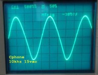
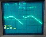
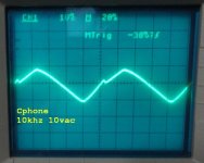
I should have investigated more closely. It is too bad that there are so many conflicting documents. The docs you sent me have two different silkscreens with totally different part numbers. The schematic you sent doesn't match the one you just posted in post #48. With that schematic I see that R38 is part of the zobel so I don't see how that can be optional. I added R38 with a 10R 2W. That got rid of the oscillation I see with no signal. However, there is still some oscillation on the bottom of a sine wave at 1khz and a notch of crossover distortion when pushed. 10khz is far worse. Square waves are pretty ugly. I'll try to get some pics up for discussion.
I should have investigated more closely. It is too bad that there are so many conflicting documents. The docs you sent me have two different silkscreens with totally different part numbers. The schematic you sent doesn't match the one you just posted in post #48. With that schematic I see that R38 is part of the zobel so I don't see how that can be optional. I added R38 with a 10R 2W. That got rid of the oscillation I see with no signal. However, there is still some oscillation on the bottom of a sine wave at 1khz and a notch of crossover distortion when pushed. 10khz is far worse. Square waves are pretty ugly. I'll try to get some pics up for discussion.
hi Terry,
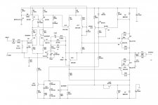
Just checked the schematic I have sent you, and indeed i did sent you the wrong schematic. Schematic in post 48 is correct. The already build Circlophones did not need the Zobel network, thats why it is set as optional.
Waiting for the scope shots.
Just checked the schematic I have sent you, and indeed i did sent you the wrong schematic. Schematic in post 48 is correct. The already build Circlophones did not need the Zobel network, thats why it is set as optional.
Waiting for the scope shots.
Here are some scope shots.
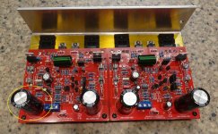
Note; my board is populated with parts matching the silk PDF except where noted above. I do see some discrepancies from the most recent schematic.
Note; my board is populated with parts matching the silk PDF except where noted above. I do see some discrepancies from the most recent schematic.
Attachments

Idle
hi Terry,
Thanks for your shots, there's an issue looking at the graphs.
Could you check the idle current please? Idle current: 150 - 200mA.
What's the DC supply voltage?
hi Terry,
Thanks for your shots, there's an issue looking at the graphs.
Could you check the idle current please? Idle current: 150 - 200mA.
What's the DC supply voltage?
Last edited:
234mA at the fuses
+-43.5V rails
What are R39 and R40? They are on the BOM and board but not on either schematic. Listed as 100R
+-43.5V rails
What are R39 and R40? They are on the BOM and board but not on either schematic. Listed as 100R
Yet another schematic with conflicting values. Someone needs to figure out what the correct values are and edit post #1. The traces and pads on these boards are not very conducive for reworking.
Terry,
The B.O.M. states R39=100kOhm, R40=100 Ohm, which matches the schematic in #1. I will re-edit the assembly doc. Please check your mail.
The B.O.M. states R39=100kOhm, R40=100 Ohm, which matches the schematic in #1. I will re-edit the assembly doc. Please check your mail.
Yes I had pad liftoff issues when I reworked some transistors and diodes. I have one board that doesn't work but have not had enough motivation to do a total rebuild with the free replacement board Piersma gave me. This amp has a prodigious amount of transistors.
Sorry, I just noticed that D3 and D7 call for a Schottky. I used MUR860. I will have to order the right parts.
- Home
- Amplifiers
- Solid State
- Inverted J-FET Circlophone Builders thread