I was on the way to solder the resistores when I stop...
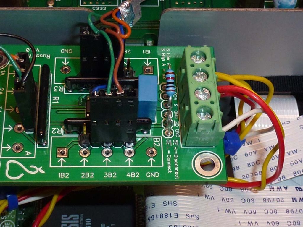
Which way should I solder the resistores? the side with the line to the squer solderpad?
Which way should I solder the resistores? the side with the line to the squer solderpad?
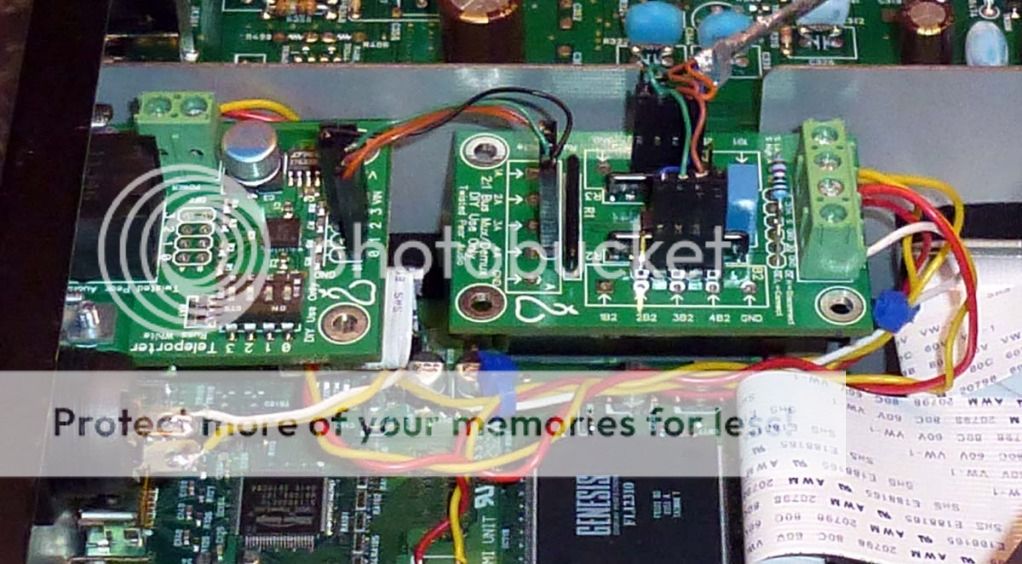
OTTO2 works great in my Denon 3910! It saved me from having to build a multiple relay board to get my R and L channels proper with SACD. DSD shares two inputs with PCM into the PCM1796 DAC chip in the 3910, but the R and L channels reverse in DSD. I just connected PCM to B1 and changed the connection order for DSD on the B2 side and that solved my R and L channel swap problem. A Twisted Pear Teleporter exports the signals to my Buffalo III DAC, soon to become a dual mono BIII.🙂
Last edited:
Hi there, Just got my OTTO 2 switch in the post today, looks like great quality. Thanks.
Just to get it straight in my head, to get it to switch need to connect the s pad to either the vcc or grd depending on which source i need to switch too?
At the moment I an using a 4:1 mux to switch between sources (non i2s obviously) this then connects to my buffalo 2 via i2s. This is switched using a rotary switch as per the diagram on the TP site. The only difference being that I don't use the the AES/EBU connection.
What I would ideally like is to connect the 4:1 to the 'A' channel of the Otto 2 and my i2s (wave io) source to the 'B' channel. Then the otto to be on 'A' whenever I have the 4:1 mux switched to any of my 3 spdif sources and then the 'B' channel of the otto to be selected when the switch is rotated to the 4th position. My question is, could I configure the switch wiring to accomplish this? Probably a stupid question with a very easy answer but my head gets in a muddle when thinking about all the pins on a switch for some reason!
Any help of connection diagrams anyone could supply would be greatly received. In fact I'd be happy to do a series of pictures and diagrams as a manual for the TP OTTO II page as it's missing one at the moment 🙂
Thanks
Stefan Whatcott
Hi Leon, got that already, but ta. It's specifically connecting it up using my current rotary switch which controls my mux 4:1, any ideas?
Maybe if it can't be part of the switching circuit I'm using it could be triggered somehow by the 4:1 mux either having an output or not? Maybe I could use the lock led in some way. That way if there is a signal present at the mux the otto will be switched to it's output, if no signal is present and hence no led voltage the otto switches the other way? That seems like a plan, and still not sure how to actually plement it though.
Thanks so far.
Stefan
Thanks so far.
Stefan
Ok, no bites. I'll try and simplify it a bit.
Is the s pad basicaly a sense circuit?
If so, theoreticaly could the vdd output for the switch circuit on the 4:1 trigger it?
Thisbis my first time on this forum, i normally hang lut at PFM. Do the guys from TP frequent these pages? Is the the best place to get support from them?
Stefan
Is the s pad basicaly a sense circuit?
If so, theoreticaly could the vdd output for the switch circuit on the 4:1 trigger it?
Thisbis my first time on this forum, i normally hang lut at PFM. Do the guys from TP frequent these pages? Is the the best place to get support from them?
Stefan
"S" stands for switch.
It takes LVTTL input. It does not matter where it comes from. 🙂 That is your choice.
I would have answered sooner, but I did not got a post notification for some reason...
It takes LVTTL input. It does not matter where it comes from. 🙂 That is your choice.
I would have answered sooner, but I did not got a post notification for some reason...
"S" stands for switch.
It takes LVTTL input. It does not matter where it comes from. 🙂 That is your choice.
I would have answered sooner, but I did not got a post notification for some reason...
Thanks Russ, that's great, as mentioned earlier, I have a 'spare' way on my 4:1 mux. I was intending on routing this vdd from the mux via the switch to the 's' pad. Would it need to go via a resistor? Presumably I don't need to tie the gdn from the mux over to the otto as well?
I like the way this forum sends you a notification when someone answers. PFM uses the same software but I don't get notifications from there 🙄
Thanks for helping out.
Stefan
You always need to make sure two circuits that share logic are at the same ground potential. The means connecting GND. Unless you use some sort of isolation. 🙂
I would keep the S input at 3.3V max.
I would keep the S input at 3.3V max.
You always need to make sure two circuits that share logic are at the same ground potential. The means connecting GND. Unless you use some sort of isolation. 🙂
I would keep the S input at 3.3V max.
I would keep the S input at 3.3V max.
Great, i think these two circuits will share a transformer, so gdn will be connected. What is the current draw of the switch so that i can calculate the value of pull down resistor? I presume the switch vdd from the mux has the same voltage as the psu feeding it?
Thanks Russ, good work.
Stefan
Thanks Russ, good work.
Stefan
It is a logic input, high impedance. You would need a voltage divider or level shifter if your starting voltage is > 3v3V. Say 5V.
Hi,
does OTTO will switch with no problem when both of source have different audio format output? (source A format 16 bit/44.1kHz while B format 24 bit/96kHz)
And will that kind of config will make problem when to be used with Metronome?
thanks
Nicko
does OTTO will switch with no problem when both of source have different audio format output? (source A format 16 bit/44.1kHz while B format 24 bit/96kHz)
And will that kind of config will make problem when to be used with Metronome?
thanks
Nicko
It does easily pass two different input signals.
The second part of your question is less straightforward. It will depend on unknown parameters.
The second part of your question is less straightforward. It will depend on unknown parameters.
Thanks for the answer, from what i experienced when used that config with Metronome before Opus made problem for source with 44.1 kHz format, the sound sometimes not came through or the sound skip a lot.
But when direct from OTTO to Opus the sound came out normally.
thanks
Nicko
But when direct from OTTO to Opus the sound came out normally.
thanks
Nicko
Any issues with chaining OTTO's? I have a USB to i2s converter, the MUX, and the DSD output from my SACD player via Teleporter to input to my Buffalo II. I thought I could use one OTTO to switch between the MUX and the SACD and output to another OTTO to switch between OTTO #1 and the USB to i2s converter. Would this cause any problems?
Stated more simply, three i2s sources(1, 2, 3), two OTTOS(A, B).
1 & 2 switched with OTTO A.
3 and OTTO A switched with OTTO B connected to the Buffalo II.
I could keep all the wires very short, stacking the OTTOS.
Thank you for your time and help.
-Aaron.
Stated more simply, three i2s sources(1, 2, 3), two OTTOS(A, B).
1 & 2 switched with OTTO A.
3 and OTTO A switched with OTTO B connected to the Buffalo II.
I could keep all the wires very short, stacking the OTTOS.
Thank you for your time and help.
-Aaron.
- Home
- More Vendors...
- Twisted Pear
- Introducing OTTO2