size & application with basic calculation for the crossover-frequencies + the datasheet. in other words: statistics.
i'll try to get a LC-meter to confirm my suspicion. but it all fits together.
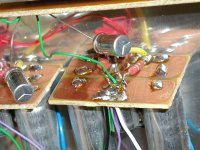
and the bipolar/polar thing: there are blue markings in the correct orientation (when polar) to denote the negative of the capacitor, but no markings on the 2u2 input capacitor. so the guys that removed the sleeves still needed some markings further down the production line 😛
Would you still be able to get an LC meter and confirm these values? I'm dying to find out these capacitor values.
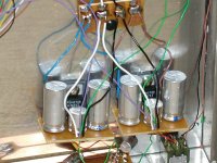
My estimation (by size and experience) is: 1000yF for the supply caps, 47yF for the FB caps and 10yF for the input cap. The supply caps of both channels are practically parallel counting up to twice the capacity, but sit individually near the ICs.
Unfortunately the LM1875 has much more output offset therefore it cannot be used without a cap in the feedback path, which would sound better.
But a lot of "voicing" or finetuning can be done via the choice of the parts used (as Peter Daniel and so many others including myself have tried). I once was more than astonished that a tiny carbon resistor sounded much better in the feedback path than the metalfilm one I had used before. Of course the Caddocks I use now are much better still. As Peter Daniel often wrote: With these chips everything counts.
There are quite a few small amplifiers in the market which are using LM1875s, but they sound more or less not very good. So construction in all details make a difference of course. A neat looking pcb design and seemingly clean soldering mean nothing per se.
My estimation (by size and experience) is: 1000yF for the supply caps, 47yF for the FB caps and 10yF for the input cap. The supply caps of both channels are practically parallel counting up to twice the capacity, but sit individually near the ICs.
Unfortunately the LM1875 has much more output offset therefore it cannot be used without a cap in the feedback path, which would sound better.
But a lot of "voicing" or finetuning can be done via the choice of the parts used (as Peter Daniel and so many others including myself have tried). I once was more than astonished that a tiny carbon resistor sounded much better in the feedback path than the metalfilm one I had used before. Of course the Caddocks I use now are much better still. As Peter Daniel often wrote: With these chips everything counts.
There are quite a few small amplifiers in the market which are using LM1875s, but they sound more or less not very good. So construction in all details make a difference of course. A neat looking pcb design and seemingly clean soldering mean nothing per se.
Thank you for your input.
For the supply rail caps, 1000uf is what stated by 47 labs, judging by their sizes in picture, it should be correct. the feedback and input cap however, is what i'm trying to figure out . based on my calculations, 2.2uf(1/(fc=1/(2*pi*22000*0.0000022)=3.29hz) for Ci and 47uf(fc=1/(2*pi*680*0.000047)=4.98hz) for Cf makes most sense for me. although i read somewhere on the forums saying that the feedback fc should be always lower than input fc. whats your opinion on this?
Attachments
It seems to be a common practice, if you use an elcap for the input the capacity should be about 10 bigger than the actual result of the calculation of the corner frequency, instead of using a foil one, where you use that value straight. I have found an explanation for this, but do not recall it at the moment.
So about 10yF seems to me about right - I use that and many others.
The feedback cap should be lower to "shift" the operating point to a "safer" area - sorry to try to explain it so un-scientifically. The detrimental effects soundwise from the feedback loop is far worse than that of the input "filter". I have tried that experimentally. So about 47yF could be right, maybe even more, about 100yF and low voltage. Low voltage caps seems to sound better here - I have tried that with certain types, but not throughly perhaps.
Can somebody identify the caps by their characteristic three-folded star on their backside?
Last edited:
10 yF? what? 10 yF = 10 *10^-24 F
are you sure you got that right?
'y' is the prefix yocto-, which is *10^-24
i am certain you wanted to use 'μF' , micro-Farad... if you can't type 'μ' then you can use 'u'. 'yF' confused me.
are you sure you got that right?
'y' is the prefix yocto-, which is *10^-24
i am certain you wanted to use 'μF' , micro-Farad... if you can't type 'μ' then you can use 'u'. 'yF' confused me.
Last edited:
Guys,
I am not trying to hold anybody back from trying small power supply capacitors but what will happen is this:
When you crank up the volume the capacitors are responsible for delivering (a part of) the current to the amp, if the capacitors are to small (they can't deliver the peak current) the voltage will drop, ultimately causing distortion of the output signal. Now this can sound o.k. if you like distorted sound but as an engineer I would rather design my power supply to match the amp..
If I want to add distortion I use a device designed to do just that in a controlled manner, a tube pre-amp for example.
Just my 2C!
you can't avoid the drop in voltage. If the capacitor provides power, its voltage will drop. Q=C V => I=C dV.
if the C is very big, the dV will be small and that is what we are trying to achieve. The capacitors are there to provide current for as long as the AC power supply's voltage is below what is requested from the amplifier
if the C is very big, the dV will be small and that is what we are trying to achieve. The capacitors are there to provide current for as long as the AC power supply's voltage is below what is requested from the amplifier
Sorry to hurt your greek feelings. It is "μF" instead of "yF", of course, but hard to type for my keyboard.
Strange story (or maybe not so strange): Long ago - when I was young - I had an amplifier with, I think, 2 x 20W or so, which had 2 x 4700μF psu caps. I thought about making it better and added another 2 x 10.000μF paralled with smaller film caps and snubbers. But the result was a definitely worse sounding amp, although it had measurably cleaner psu lines and better output specs power wise.
I am since then very sceptic about "absolute" rules. All amplifiers sound different and the reason for that is not always easy to discover.
I am since then very sceptic about "absolute" rules. All amplifiers sound different and the reason for that is not always easy to discover.
what greek feelings? just use uF... yF is a different prefix altogether and it might confuse. At least it confused me, maybe the rest of you can derive the correct value
Found this site after doing a random Google image search - assume this is the real McCoy being dismantled and copied?
ǧ¨Ã Gaincard µÑǨÃÔ§àÊÕ§¨ÃÔ§
(Language is Thai if you need to use Google Translate).
Looks like they've even copied the chassis too! 😱
ǧ¨Ã Gaincard µÑǨÃÔ§àÊÕ§¨ÃÔ§
(Language is Thai if you need to use Google Translate).
Looks like they've even copied the chassis too! 😱
Last edited:
Found this site after doing a random Google image search - assume this is the real McCoy being dismantled and copied?
ǧ¨Ã Gaincard µÑǨÃÔ§àÊÕ§¨ÃÔ§
(Language is Thai if you need to use Google Translate).
Looks like they've even copied the chassis too! 😱
Good find mate. i have mad respect for this person who had guts to take his Gaincard apart and share with us, looks like he had done a double blind test with his clone as well. This is the real deal guys, the Gaincard analysis by Mick. F did was indeed on an old version. All the newer Gaincard has the chip mounted vertically. I do still have one question though, why would he listed the input cap as 110uF!?
Yeah I was curious about that 110uF too - seems a bit excessive?! Not sure how they arrived at that value (caps are all skinned) unless they actually measured the cap out of circuit?
They've cloned the chassis too - even the controls! Looks like they have a group buy for that going! Can't decide if I admire their dedication, or question their cloning ethics
They've cloned the chassis too - even the controls! Looks like they have a group buy for that going! Can't decide if I admire their dedication, or question their cloning ethics
Good find mate. i have mad respect for this person who had guts to take his Gaincard apart and share with us, looks like he had done a double blind test with his clone as well. This is the real deal guys, the Gaincard analysis by Mick. F did was indeed on an old version. All the newer Gaincard has the chip mounted vertically. I do still have one question though, why would he listed the input cap as 110uF!?
Reading the Google translation of the mentioned thai forum into german language made my day!
(lots of fire, tigers and temples...)
I did not find out some facts they use (nevertheless...):
The brand of capacitors. They are also unmarked, so they use bipolars also for supply??
Brand of resistors?
Maybe there is another blog whare these facts are discussed. Can somebody thai speaking give a short summary of the facts and the results?
Attachments

And none of you commented on the exposed mains terminals right next to all those exposed metallic parts !
One cm without insulation - that is bad, maybe not CE or VDE, but not that great. Mounted on the back plate there is nothing even near to get in contact to. A little bit of heatshrink tube would have done it better though.
That Thai forum is about group clone gaincard. They bought one and tare it apart,try to clone by ear. One thing from that forum is seperate R-core trafo is better than single original. For the input cap they tried 8uf solen, mundroff etc. but it is worse than 110uf electrolytic. The other clue is that chip should operate at 70 c. Also vibration do have affect in sound that is why they tried to clone the box too.
- Status
- Not open for further replies.
- Home
- Amplifiers
- Chip Amps
- internals 47 labs 4717 integrated