Hi all,
So I'm looking for ways to absorb a fairly narrow range of frequencies within a cabinet, so that the output from the port (or horn, I suppose) has a notch there. It'd be for things like preventing the excitation of the 1/4-wave resonances of a long bass reflex port.
It looks like a small Helmholtz chamber might do the job, but I also suspect that some PVC pipe could be used as a quarter-wave resonator.
So, if I wanted to absorb at 160Hz inside a subwoofer, is it just a case of either:
- Build a small box with a port tuned to 160Hz, and apply absorption to that box
- Get 54cm of PVC pipe (that's 1/4-wave long at 160Hz), block one end and fill with stuffing
?
I'm certain that there are other things to consider and while I've seen hints at things in other threads, I haven't yet seen them explicitly discussed.
Does the cross-sectional area of the port/pipe make much difference? What about at high power levels?
TIA,
Chris
Car guys seem to attach quarter wave resonator pipe to silence drone. Google finds lots of info, for example Problem - Exhaust drone: Solution side branch, aka 1/4 wave resonator, or Helmholtz resonator| Grassroots Motorsports forum |
Some empirical test here for such pipe for high speed exhaust gas flow
http://data.mecheng.adelaide.edu.au.../2014/preprint_howard_aa_2014_branch_geom.pdf
I posted some test results on another thread that simple perforations in the reflex port seems to kill some midrange leakage. I have no idea how it behaves with high power. Hopefully fruitfull discussion emerges")
Some empirical test here for such pipe for high speed exhaust gas flow
http://data.mecheng.adelaide.edu.au.../2014/preprint_howard_aa_2014_branch_geom.pdf
I posted some test results on another thread that simple perforations in the reflex port seems to kill some midrange leakage. I have no idea how it behaves with high power. Hopefully fruitfull discussion emerges
Last edited:
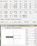
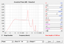
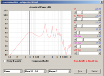
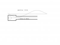
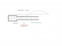
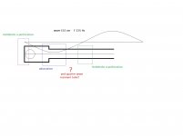
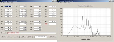
Just tryed something...Example of damping a port with a 37cm 44cm² stub at half-way of the port in a stupid sim of a 4th order bandpass with big resonnance around 220hz. Effect seen using hornresp simulating as OD1. It's a 40 liter closed back chamber, 14 liter front chamber, 140cm² port of 75cm long. It sims good, with/without the grey stuffed stub, in grey/red in picture 2 ^^ It damp too the lower 600hz resonnance.
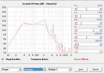
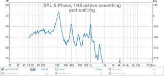
EDIT : Damping near the end of the port in picture 3 seems to get ride of 400hz spike but curves is les regular. Don't know how to damp both right...would need to play with Akabak
EDIT : Damping near the end of the port in picture 3 seems to get ride of 400hz spike but curves is les regular. Don't know how to damp both right...would need to play with Akabak
Attachments
Last edited:
Helmholtz and 1/4 wavelength resonators are similar, like vented and 'transmission line' loudspeakers are similar. A disadvantage of a 1/4 wavelength resonator is that it also resonates at 3/4 and 5/4 wavelength etc.
Increasing size of the resonator increases absorption. The amount of stuffing controls the quality factor: less stuffing means more absorption at a smaller bandwidth. Regarding air velocities, I would expect the same guide lines apply as for ports in vented loudspeakers, though chuffing might be irrelevant while port compression remains relevant.
If port resonance is a problem, you could consider adding an acoustic low pass filter between the woofer and port. A panel with a hole in it might work.
Last edited:
It doesn't seems to work at all in hornresp. And a low pass, low pass everything, affecting a lot phase, and should be well calculated to not make crossing with higher way hell of a work.A panel with a hole in it might work.
I'm looking for ways to absorb a fairly narrow range of frequencies within a cabinet, so that the output from the port (or horn, I suppose) has a notch there
Didn't found what i wanted but here some stuff...Forgive me, it was 10 years ago ^^
With photos here : lilmike's Shiva X2 Tapped Horn - Page 4 - AVS Forum | Home Theater Discussions And Reviews
David McBean: Hi David, first thanks you for the latest update of Hornresp, another useful feature, and a very impressive list of revisions.
As Eva has been so successful -
The Danley patent - as referenced by Marcello in the collaborative tapped horn thread - shows the inside of the TOP in Fig.8 and Fig.9. The same construction method seems to have been applied
to the DTS-20.
The sequence of the forward acoustic flow is:
- driver front
- compression chamber
- horn throat
- horn run driver front to back
- horn run driver back to mouth.
There is no S1 to S2 section.
From the photographs of the inside of the DTS-20 it is obvious, that at least two resonance pipes are being employed.
At present this tapped horn configuration cannot be modeled in Hornresp. Is there any hope for adding at least the front compression chamber, e.g.: in front of the S1 to S2 section, with the respective relocation of the driver to S1 when this feature is used? I realize, that it is possible to minimize the impact of the S1 to S2 section in the current model, but with such a fine piece of software that just about makes me cringe.
Not being a programmer, I have no real idea of what I just asked, and I should probably find some early morning hours to learn how to use AkAbak.........
Thanks again, bye for now.
Here's my take on the resonators.
1. They are absolutely required to get more bandwidth than the average diy tapped horn. This part is obvious enough. The commercial models are getting at least an octave more than any diy design I've seen.
2. Without the extra bandwidth that the resonators provide, a 6th order bandpass can do approximately the same spl (or more) and similar bandwidth (maybe a bit less) in the same size package. The only advantage the average diy tapped horn has over 6th order bandpass is no port compression.
3. I suspect the resonator opening must be placed very carefully to get full effect. If my theory about the placement can indeed be visualized by the rubens tube effect, there may actually be several optimal places to locate the opening, but precise placement on one of the standing waves of the problem frequency is still paramount.
4. The dts-20 uses lengths of pipe for resonators. I have no idea how long they are. Pipes obviously have pipe resonances, so if a single long skinny resonator is used it may possibly be persuaded to kill both of the tapped horns twin peaks. That would be a handy little trick indeed. But it would not be a trivial task to design, for me at least. There are helmholtz calculators online but IIRC they only calculate frequency vs volume and do not take shape into account. So the volume AND shape of the resonators may be critcal as well as the placement issue.
Maybe I'm overthinking this, but IMO it's best to be prepared for what could happen during prototype testing. Personally I'm going to hold off on learning akabak as long as possible, opting for real physical tests and measurements instead. I'm going to take pipes of different cross sectional areas and lengths (with one end covered) and shove them up the backside of my bib and do a series of measurements at different positions in the line, probably inch by inch until I have a sweet spot and then cm by cm. Each different pipe I test will have the approximate helmholtz resonance frequency as the first tapped horn peak as an initial starting point.
That should give you a bit to chew on, but since my methodology is not scientific and I won't be able to actually confirm anything without learning akabak, and because there is almost zero interest in this area I'm not going to press this issue any further.
With photos here : lilmike's Shiva X2 Tapped Horn - Page 4 - AVS Forum | Home Theater Discussions And Reviews
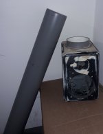
asked similar at the FR forum but with regard to figuring a smoothing stub for a Karlson type. Some years back, I added a 20 liter stub to a small 18K front chamber (seen at the right) rear chamber IIRC was ~80 liter. I need to have a decent fudge of stub volume as its useful to counter reflections and a cavity peak which can be excessive.

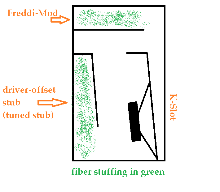
MMJ fudged K model

MMJ fudged K model
Last edited:
- Status
- This old topic is closed. If you want to reopen this topic, contact a moderator using the "Report Post" button.
- Home
- Loudspeakers
- Subwoofers
- Internal narrow-band absorption techniques?