Are we sure the the tl072 is where the audio signal enters?Just trying to rule some things out because its drawing excessive current.The square wave output is very sloppy.I changed both transistors on the board as well.Initially it would draw excessive current and have sloppy square wave output when I wiggled the board.Now its consistently drawing excessive current lol.
from what i ve seen in other modules, yes.
It is possible that its not not a TL072 but a TL071. You can check this by checking if both ics det +5V at pin8.
If one has +5V at pin 7, its TL071
It is possible that its not not a TL072 but a TL071. You can check this by checking if both ics det +5V at pin8.
If one has +5V at pin 7, its TL071
Both have voltage at voltage at pins 4 and 8.With the driver board removed.The little board is generating a squarewave if I drive a signal into it.Maybe I have another problem on audio driver board.This thing has been so back and forth.
I would assume everything is okay with little ic board since it does produce square wave with audio input?
I would assume everything is okay with little ic board since it does produce square wave with audio input?
I don't understand why there is 4.6vdc+ on output of ic driver board with no input signal.Wouldn't this try to turn on all the outputs upon power up?
When input a 100hz signal the voltage drops to .200 and produces a squarewave.
When input a 100hz signal the voltage drops to .200 and produces a squarewave.
Post #14:
You can confirm that the other is an LM211 by measuring the resistance between legs 1 and 4. In this circuit, the LM211 has those two legs directly connected (0 ohms). (from the class D - Type 3 page.
For clarification, the driver board is the board that drives the outputs. The small board that you removed is the modulator board.
I was looking in class D 4...Anyhow,feel like I'm stuck between a rock and rock.I'm not entirely sure which board is causing problem now.Especially after this thing ran great for 20 minutes.
Everything seems well on modulator board.Replaced both ic's and transistors.It will produce a squarewave with input signal(audio board removed).
With audio driver board installed it produces a very blurry squarewave to outputs and draws tons of current.
Before I changed any parts on modular board the amp powered up and I had good signal on all outputs except 2 low side sets.Traced back and found,replaced drivers.
Reinstalled audio driver board and amp ran fine.Turned it off,turned it back on and started drawing excessive current.When I wiggled the modulator board I get the amp to change current draw.
Perhaps I missed something on audio driver board.I can remove either or and amp powers up.With both boards installed it drags the 5 volts to the modulator board wayyyy down.I'm assuming the audio board can cause that issue affecting modulator board.
Do you see a 5v line going to the driver board?
Are you sure that you don't have any defective vias for either board?
Are you sure that you don't have any defective vias for either board?
Yes I have 5 vDC +/- entering modular board.Have all my voltages entering audio driver as well.
Not sure if this matters or helps.Without input signal and without audio board.The output of the modular board has nearly 5vdc+.I wish I knew if that meant something.
With input signal.The modular board output is perfect squarewave although, the 100hz signal into modular has severe crossover distortion.Not sure that matters at the moment.Because when I turn the amp on with no input signal it draws excessive current.
If I pull either board,it will power up.
Now wiggling the modular board makes no difference.I did confirm continuity of all 5 vias top and bottom twice to there locations.
Hello Sirs,
I'm new to this forum, I searching for this amplifier repair and I came to this
My problem with the same amp is that small board that's inside the epoxy box, I tryed to remove the epoxy and retain the small pcb intact but I couldn't retain the small ics. Does anyone knows the numbers of the U1 and U2? Are theese Tl072 and Lm211? and whick one is for u1 and whick for u2. Any hepl would be appriciated
Greeting from Greece
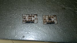
Here is the picture of the pcb without the epoxy.
U1 is on the right U2 in on the left
It write's on it woofer module v30 3s tech.
U1 is on the right U2 in on the left
It write's on it woofer module v30 3s tech.
Attachments

Last edited:
- Status
- Not open for further replies.
- Home
- General Interest
- Car Audio
- Interfire 2000D oscillation