Having tried Fairchild HGTG40N60A4 also, it gave me higher losses when hard switched at 125k. IXYS is costly but its very reliable and never got damaged even when pushed to its current limits. IXGH60N60C2D1 is available with optional inbuilt diode. 😎
Last edited:
Workhorse,
looks really great !!!
wow ... 5kW@2ohms, it's similar to what I want (2,4kW@4)
But you have to deal with more current in your design. How did you manage with the PCB ?
The PCB I'm making have some similarity with yours, power and filter on big board, signal and control on a board placed in right angle.
Can I ask what is [3-level PWM] ?
I'm now searching for the components but struggling to find bigger cores for the output filter. Please, can someone suggest where to find/buy ?
The PCB i am using is made from more than 75u copper thickness with added reinforced copper conductor for high current tracks.
This module is full range one not LF, thankz to 3-level PWM . Try www.cwsbytemark.com for cores
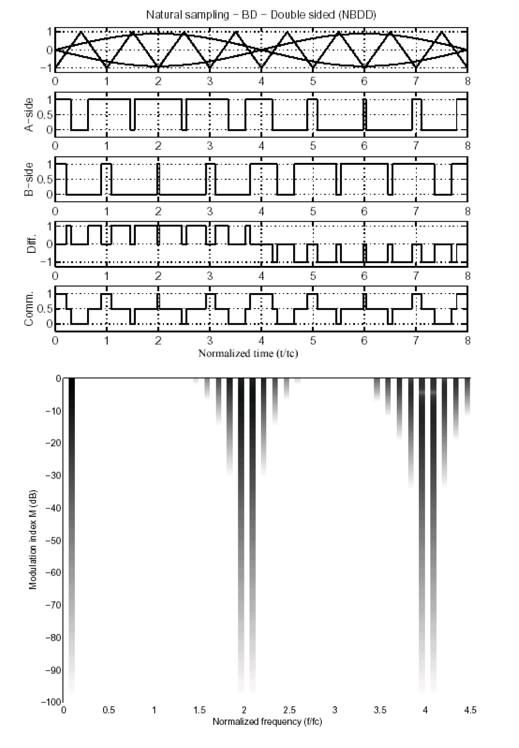
This is 3-level PWM BD mode
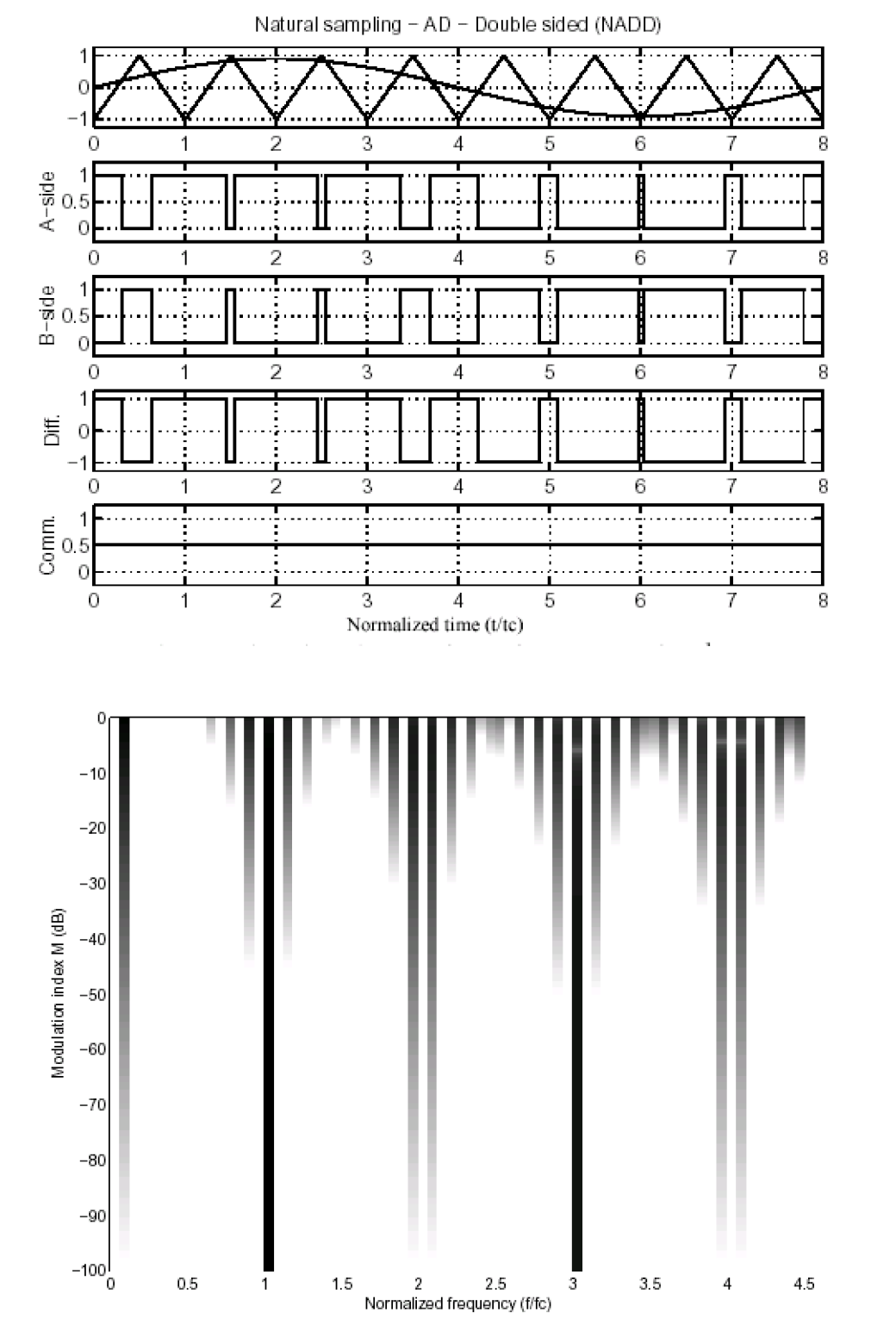
This is normal 2 level PWM AD mode
Last edited:
Workhorse,
thank you for the info, where can I get more information? How is the feedback part managed?
thank you for the info, where can I get more information? How is the feedback part managed?
I have been searching some patents, and it looks very promising. Feedback is also quite easy.
Well, modification will only be on the signal and control board. Maybe I will step ahead and use a DSP to generate the PWM signals I need.
Well now I feel like a child that wants to play with his new toys.
Thank you again Workhorse !
Well, modification will only be on the signal and control board. Maybe I will step ahead and use a DSP to generate the PWM signals I need.
Well now I feel like a child that wants to play with his new toys.
Thank you again Workhorse !
DSP for audio PWM is not a great idea, the time resolution needed even for CD dynamic range is prohibitive...
DSP for audio PWM is not a great idea, the time resolution needed even for CD dynamic range is prohibitive...
Hello Eva,
I have been around here for some time. But starting just now with the class D subject, because just now I have some time to spend. I have finished my Eng. course (Computer Networks) and have time till the end of the year. I'm not that comfortable in electronics, but I like it very much.
First priority is to make a basic LF Amp, 2x IRS21844 and 4x IXGH60N60C2D1 to make the H-bridge, a bunch of amp ops for the analogue part and a comparator. Is there any problem to use an external oscillator to test different osc. frequencies ? I already finished the PCB's and now I'm waiting to arrive.
Next step, assemble the PCB's, testing, failing, trying and learning ... this will be the fun part.
If everything goes well, I will try Workhorse approach with the 3 level PWM.
The DSP part could be a mixed solution, I have worked with some Analog Sigma DSP's ( I don't see the need of an powerfull DSP for this). One of my thoughts was to generate a nice triangle on one of the GPIO ports (can go up till 96khz) and have the audio signal out of the DAC. The PWM would be made over the comparator. Feedback could be returned over the ADC's (maybe the tricky part).
But this will be the very last Part, in between I have to think about the Powersupply (Buy or make ). The power supply at the university is not mine and also not very lightweight (85kg).
The architecture you are planning is all wrong for audio, starting by the IRS21844 driver with 400ns mandatory dead time... Check IR2110/2113. High/low side timing control must be manual/discrete to tailor it to each circuit. Audible distortion is produced otherwise.
What in the hell are they teaching in engineering courses? By the sound of many posts it's completely useless for anything but low precision purposes like motor speed control! It's outdated/low-grade knowledge.
What in the hell are they teaching in engineering courses? By the sound of many posts it's completely useless for anything but low precision purposes like motor speed control! It's outdated/low-grade knowledge.
What in the hell are they teaching in engineering courses? By the sound of many posts it's completely useless for anything but low precision purposes like motor speed control! It's outdated/low-grade knowledge.
Eva,
They teach allot of theory. But I was sad that the electronic subject was very basic (No, they don't cover power electronics for motor control).
I want to start with the worst case scenario. At 35kHz it should work. Yes, I was thinking of the IR211x, too. Want to see and learn what happen.
But I want to say that I highly respect and appreciate any comment that will teach me how things are!
Celsosc,
First try some simple Class-D concepts rather than going for something which is complex for you.
First try some simple Class-D concepts rather than going for something which is complex for you.
If you want digital PWM generation an FPGA would be the way to go. Cyclone 4's are available quite cheaply at the moment from terasic. Something like a 5th order delta sigma modulator could work out quite well but getting decent efficiency from a discrete time system while having good quality is going to be a nightmare as it's inevitable your average switching frequancy for the same dynamic range as a continuous time system is going to be greater. Personally after recently smoking a PD12SB30 with a more modest 1.75Kw amplifier (EP4000) I would hesitate to build such a high power amp as almost all speakers will fail very very quickly at such a power level.
As an electronic engineer I find modulation schemes more interesting than the power stage so just reusing an existing full bridge and strapping on an FPGA would be the way I would go. Add on a high speed ADC to monitor pulse shape for feed forward correction and another looking at the speaker for overall feedback. Fun!
As an electronic engineer I find modulation schemes more interesting than the power stage so just reusing an existing full bridge and strapping on an FPGA would be the way I would go. Add on a high speed ADC to monitor pulse shape for feed forward correction and another looking at the speaker for overall feedback. Fun!
Celsosc,
First try some simple Class-D concepts rather than going for something which is complex for you.
Don't be worry about the complexity, the last time I was told not to do something resulted in:

My "little" class AB amp, not efficient at all ... but sounds so nice. The picture was taken when I was building it, there are some parts missing.
Last edited:
Personally after recently smoking a PD12SB30 with a more modest 1.75Kw amplifier (EP4000)
Hello Kipman,
Do you have a picture of the voicecoil from the smoked PD ?
Workhorse, are those diagrams from an old AES paper?
Whether, I'm finding the spectral graphs difficult to interpret.
Whether, I'm finding the spectral graphs difficult to interpret.
Of course many of us made it. For examle this is an older design of me. Only 800 W @ 8 ohm, but can operate without fan. (5 W idle loss in amp, 10 W in PSU).
View attachment 243299
In the latest version (which is already 1 year old) I tried FGH50N3 and some 88N30 MOSFET (with diode bypass), and they both worked well, 1200 W @ 4 ohms.
View attachment 243305
fsw=150 kHz
Do you like to share this schematic? Im interested
Don't be worry about the complexity, the last time I was told not to do something resulted in:
My "little" class AB amp, not efficient at all ... but sounds so nice. The picture was taken when I was building it, there are some parts missing.
do you like to share this schematic ?
do you like to share this schematic ?
NMOS,
I builded it long time ago, back in 2000. I will try to find the schematic, but it's almost identical to QSC's mx700 schematic but a little overpowered with 90V rails.
Don't be worry about the complexity, the last time I was told not to do something resulted in:
My "little" class AB amp, not efficient at all ... but sounds so nice. The picture was taken when I was building it, there are some parts missing.
Thats an easy QSC grounded collector clone AB amp, not a complex thing to do.
Workhorse, are those diagrams from an old AES paper?
Whether, I'm finding the spectral graphs difficult to interpret.
Yes, its from Karsten Nielsen AES paper on active pulse modulated transducer. You need to learn about histograms
I know that the thread is about IGBT.
But what about IXFH40N50Q2?
500V,40A, extremely fast switching times, with a decent 250nS max body diode
Check out the datasheet:
http://www.farnell.com/datasheets/42419.pdf
br,
savu
But what about IXFH40N50Q2?
500V,40A, extremely fast switching times, with a decent 250nS max body diode
Check out the datasheet:
http://www.farnell.com/datasheets/42419.pdf
br,
savu
- Home
- Amplifiers
- Class D
- Interesting IGBT for class d...