'The zener effect' does not dominate at any voltage, there aren't any more zeners at 5V than at 50.
Would be wiser to learn before write.
Zener and Avalanche Breakdown/Diodes
"In a 'Zener' diode either or both breakdown mechanisms may be present. At low doping levels and higher voltages the avalanche mechanism dominates while at heavy doping levels and lower voltages the Zener mechanism dominates. At a certain doping level and around 6 V for Si, both mechanism are present with temperature coefficients that just cancel."
If you expect the MOSFETs to see 80V peak, then pick a 100V rated MOSFET. If it will see 100V you must pick one with a rating of 120V, etc,etc.
I will not sacrifice all of the important parameters (Rdson, diode trr, Qg...) of a MOSFET just to make your fears for avalanche justified.
Nobody designs an amp with the assumption the MOSFET's avalache capability will handle the higher voltages than waht the FET is rated for.
Only the designers who know electronics.
That avalache diode is nothing anybody designing amps should even bother thinking teeny weeny bits about.
Most times you should not bother because it is designed well by semiconductor designers.
Avalanche Breakdown when intentionally used can be very useful.
For example, simple 2N3904 small signal BJT can utilize that and in configuration of pulse generator (supply voltage larger than 90-100V) can produce very very fast rising and falling edges, in order better than 1ns, I measure around 850ps rising edge with my equipment.
Tunell diodes also utilize that behavior for oscillators and amplifiers for operation in range of many GHz.
Avalanche Breakdown when intentionally used can be very useful.
Nice example here : Picosecond Pulser | SiliconValleyGarage | Vincent Himpe
Allright Pafi you obviously have experience using the avalanche capability of MOSFETs. Very interesting and I will look more into it. This is new to me. In the smps seminars I have attended good design has focused on derating the MOSFET and I cannot recall mentions of using the avalanche capability of transistors. Robust design rules recommend at least 50% derating. In my little experience with switching power ckts its been the over voltage situations that blow up the design. Higher voltage rated FET and/or snubber fixed it. Perhaps b/c I mostly design for switch frequencies over 500kHz and seldom very high power.
Is the avalanche effect more commonly used in higher power and lower frequencies?
In defence of myself I will say in all cases Ive experience mention of FETs body diode it is universally understood it is the inherent body diode in all MOSFETs.
Besides you do not buy a 51V 'avalanche' diode. You buy a 51V 'zener'.
Interesting - so how to know what the breakdown voltage is when its not shown in the DS? Also what's the temperature coefficient of the breakdown voltage?
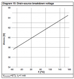
I just find one DS for IPD025N06N MOS-FET (60V device) and there is one diagram showing temperature dependency on device's breakdown voltage.
Attachments
Thanks for sharing that. However its a result which, on the surface doesn't harmonize very well with earlier statements about breakdown voltage. Pafi said its 1.1 to 1.3X the breakdown so are we to assume the dynamic resistance is rather high?
Thanks for sharing that. However its a result which, on the surface doesn't harmonize very well with earlier statements about breakdown voltage. Pafi said its 1.1 to 1.3X the breakdown so are we to assume the dynamic resistance is rather high?
As you said, on the surface. Then let's dig into the datasheet!
60 V is stated as minimum value in Table4 (at Tj=25 C as stated on the top of page 2). Since Diagram 15 shows the same value, it must also be minimum value.
I didn't measure minimum value, only 3-4 samples of a type, this is obviously somewhat higher. (And not for every one of the manufactured types of the whole world, only some of my preferred or interesting types. There can be exclusions.)
I generally measured it with 1...30 mA, but in this domain I experienced insignificant voltage change (insignificant for the normal application - I don't use them as high performance voltage stabiliser).
High dynamic resistance? I don't know what could be the logic behind this conclusion, and also what can be considered high for you. It is generally low enough to limit Vds voltage to under about 1.5*Vdsmax at Idmax.
- Status
- Not open for further replies.
- Home
- Amplifiers
- Class D
- Interchangeable mosfets?