Hi All
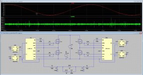
I have a strange outcome from a simulation, the output is just fine, Get a nice sinusoidal signal, but when probing before the low pass filters on output mosfets I get voltagespikes into the tens of kilovolts. I see no switching action, but it do because I have demodulated output and it is on 800 Khz.
It is a floating output did put some big resistors on it, that did not help.
regards
Attachments
Last edited:
Yes you are right. 🙁
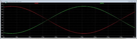
Here the new ones, I have included the same version but now with pwm-out2 grounded and also the speaker out.
However when pwm-out is grounded there is no signal for the bootstrap circuit, need active one.
Then it go well as you see, so floating errors?
regards
Here the new ones, I have included the same version but now with pwm-out2 grounded and also the speaker out.
However when pwm-out is grounded there is no signal for the bootstrap circuit, need active one.
Then it go well as you see, so floating errors?
regards
Attachments
Last edited:
It's difficult to imagine how signal pwm-out1 can fall to 20 kilovolts below ground, when the drain-to-bulk "body diode" of the lower MOSFET is connected between pwm-out1 and 0V. We'd expect to see it fall no lower than -0.8 to -0.9 volts. Maybe you've got an unexpectedly high impedance ground network.
_
_
Attachments

No idea if it applies here, but I have seen similar things in my high voltage amplifier. I fixed it by checking the Tools|Control Panel|ASCII data files check box.
I know, a long shot, but apparently a known bug 😉
Jan
I know, a long shot, but apparently a known bug 😉
Jan
Hi kees52,
Try adding shunt resistors across C4 and C5. 1Meg ot 1G
As well as that try shunt resistance for L1 and L5, eg 1 Meg (or less?).
BTW set .Options Plotwinsize=0
Ian
Try adding shunt resistors across C4 and C5. 1Meg ot 1G
As well as that try shunt resistance for L1 and L5, eg 1 Meg (or less?).
BTW set .Options Plotwinsize=0
Ian
It is a multilevel cascade pwm, so gatedrive and mosfets are floating.
I get by the way a normal output 1 khz 8 amps in 8 ohms.
The four iso7710 are insolated to the gatedrivers, so vss is floating..
I get by the way a normal output 1 khz 8 amps in 8 ohms.
The four iso7710 are insolated to the gatedrivers, so vss is floating..
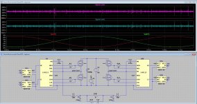
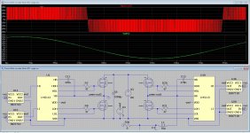
I have change the circuit like this, because it works then for single output and not btl by reference the sources of U8 and U9 to ground, but one things does not work, the bootstrap has that way no boost on one side, but ot does simulate right this way.
Setting the bootstrap to a other point with pwm the fase get corrupted and three level is lost.
The high voltages on the nodes are gone that way, but strange is that both does simulate with normal outputs a 1Khz and 180 out of fase in the btl failing version.
the shunt resistors did not work.
Can try in the old 32bit version of ltspice, just curiousity?.
Attachments

Then connect the VSS to ground with a 1 - 2 pF capacitor and a leakage resistance of 1 GigaOhm (Rpar=1G in capacitor parameters). You will not deny that there is always a capacitance between VSS and GND. Both for optocouplers and for transformers. That would help. I even made an element - a floating ground on such a principle. Give it a try. That should help.
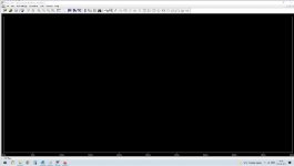
my spice programme has stopped working, any ideas? when i open a file i just get a black screen
Last edited:
What happens if you just open LT without opening a file? Just click the program shortcut.
Never heard of anything like this happening tbh.
Never heard of anything like this happening tbh.
my spice programme has stopped working, any ideas? when i open a file i just get a black screen
Just download it and re-install.
Jan


Hard to make that out but it looks like a graph or plot pane. Have you saved the .asc file together with plot settings? If so it might be auto running and waiting for you to make the next move 🙂
What happens if you just click the program executable shortcut? Don't click a .asc.
You should have that somewhere like the desktop or start menu.
What happens if you just click the program executable shortcut? Don't click a .asc.
You should have that somewhere like the desktop or start menu.
Here is the image blown up. I can see it is the Europa amp. Look where you have saved the files and see if you can see any .PLT files like these. PLT files will auto run the simulation.
I don't think there is anything wrong with the LT install from what I see.
My turn to watch TV... DCI Banks. Good luck, I'll look in tomorrow.
I don't think there is anything wrong with the LT install from what I see.
My turn to watch TV... DCI Banks. Good luck, I'll look in tomorrow.
Attachments

- Home
- Design & Build
- Software Tools
- Installing and using LTspice IV (now including LTXVII), From beginner to advanced