Thanks 🙂
I've taken your circuit and swapped the models for the standard LT library ones. You can alter these back to suit yourself. The vbe (vgs) multiplier transistor was missing and I've set the bias to around 100ma. I set the run time for 8ms and the timestep to 0.000000030517578125 which was just copy and pasted from Windows calculator (10ms/262144).
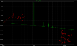
Level set to give 1 watt into 8 ohm.
I've taken your circuit and swapped the models for the standard LT library ones. You can alter these back to suit yourself. The vbe (vgs) multiplier transistor was missing and I've set the bias to around 100ma. I set the run time for 8ms and the timestep to 0.000000030517578125 which was just copy and pasted from Windows calculator (10ms/262144).
Level set to give 1 watt into 8 ohm.
Attachments

Thanks again!
Thank you very much! Mooly.
I'll solder amplifier ...
(Oh, need to learn more in detail LTspice...)
Thank you very much! Mooly.
I'll solder amplifier ...
(Oh, need to learn more in detail LTspice...)
My First LTSpice Model
I am very new to this software. Recently I built a TubeLab SSE amplifier and attempted to model it in LTSpice. I learned a lot from this forum and the model seems to be working well. I have to admit a few of the components I literally copied from George's LTSpice jpegs and some others. One of my main concerns is the output transformer. I have Trancendar 5k 8R 10W transformers. I am not looking to model them in detail, I know I can download and create very elaborately designed .inc models. I really just want to understand how to convert what I know about the transformers to the coupled multi inductor method suggested by LT Spice, using Henerys and the other perimeters. I would love some suggestions, advice, direction? Thanks! 🙂
I am very new to this software. Recently I built a TubeLab SSE amplifier and attempted to model it in LTSpice. I learned a lot from this forum and the model seems to be working well. I have to admit a few of the components I literally copied from George's LTSpice jpegs and some others. One of my main concerns is the output transformer. I have Trancendar 5k 8R 10W transformers. I am not looking to model them in detail, I know I can download and create very elaborately designed .inc models. I really just want to understand how to convert what I know about the transformers to the coupled multi inductor method suggested by LT Spice, using Henerys and the other perimeters. I would love some suggestions, advice, direction? Thanks! 🙂
An externally hosted image should be here but it was not working when we last tested it.
An externally hosted image should be here but it was not working when we last tested it.
Modelling transformers is outside my sphere of expertise I'm afraid but hopefully others may be able to give you some pointers.
Just do a search on the Tubes-Valves forum, there are a bunch of threads on the subject, even Excel worksheets.what I know about the transformers to the coupled multi inductor method suggested by LT Spice, using Henerys and the other perimeters. I would love some suggestions, advice, direction? Thanks! 🙂
Mooly - please find some time, and make demo analysis IMD for "One transistor amp", when tested two frequencies e.g. 19 and 20 kHz.
((If i ask too much - sorry, and understand refusal.))
((If i ask too much - sorry, and understand refusal.))
Observed changes to LTspice following update.
I've noticed a couple different modes of behaviour with my LT installation running on W8.1 following an update. This behaviour is also mirrored on a Vista install.
1/ When renaming an open sim file that has already been run and that has generated temp files (.raw etc), closing the newly renamed file now deletes the .raw data generated from the initial sim. That never used to happen before. Even though I use the settings outlined in post #1 and have LT set to auto delete these files, renaming an open file always removed the dependency leaving the files behind. Now it does not. This is much better imo.
2/ When opening LT by just clicking a sim file rather than opening that file from an already running LTspice I used to encounter a message of 'the command could not be sent to the program' (which if you clicked OK actually worked anyway). Now I am not seeing that message. It opens directly.
Transient plot setting for low THD noise floor?
Hi, I need advise on how to set up a transient plot to get a good FFT noisefloor.
I have this setup for the simulator:
.param nFFT=1; for .four command
.param numcyc=30; For transient plot
.param dlycyc=1
.param Points=1000
.param simtime=(dlycyc+numcyc)/Freq
.param dlytime=dlycyc/Freq
.param BW=80k
.param Harmonics=BW/Freq
.param Timestep= 1/({Freq}*Points)
.maxstep = Timestep
But I'm not happy with my noisefloor.... what to do?
Thanks
\\\Jens
Attachments
Last edited:
lots more points in .tran, the fft and use a window function - usually I use Blackman
exact integer number of cycles of the fundamental in the record time makes windowing less important but I do both
I use very small t_max_step_size but don't do any explicit calc as long as its several times your fft analysis record length divided by # of ftt points
and sometimes you need better DC solution and/or to allow longer .tran sim time, discarding the settling time region, just analyze the last few cycles when startup transients have died down
Last edited:
lots more points in .tran, the fft and use a window function - usually I use Blackman
exact integer number of cycles of the fundamental in the record time makes windowing less important but I do both
I use very small t_max_step_size but don't do any explicit calc as long as its several times your fft analysis record length divided by # of ftt points
and sometimes you need better DC solution and/or to allow longer .tran sim time, discarding the settling time region, just analyze the last few cycles when startup transients have died down
Blackman did the trick! Thanks
In the name of learning, here are both plots, without and with Blackman window applied.
\\\Jens
Attachments


Last edited:
Yes, and you can still get rid of that slant if you find the source of drift in your circuit or use the alternate solver.
Yes, and you can still get rid of that slant if you find the source of drift in your circuit or use the alternate solver.
Thanks,
Now it is good enough to be used for tweaking 🙂
\\\Jens
Last edited:
Dear Mooly,
having read all 474 posts, I can now run LTC.
Many thanks for this thread and to the other contributors.
Whilst I don't mind copying in text model directives, i real appreciated discovering the inc directive to use Cordell's text models.
Thank you thank you.
Matthew
having read all 474 posts, I can now run LTC.
Many thanks for this thread and to the other contributors.
Whilst I don't mind copying in text model directives, i real appreciated discovering the inc directive to use Cordell's text models.
Thank you thank you.
Matthew
Help getting IRF820 model to work in LTspice
I'm trying to get an IRF820 model working in LTspice.
The model I'm using (in the file IRF820.inc, in my \lib\sub\ directory):
I've tried to use it with a generic MOSFET model, listing this file (IRF820.inc) in a file named IRF820.asy, like so:
As it says, it does not work. What am I doing wrong?
Also, does anyone have an IRF820 or IRFBC20 model that can go in the standard.mos file? That's the type that would start with .MODEL
Thanks for any help.
- RG
I'm trying to get an IRF820 model working in LTspice.
The model I'm using (in the file IRF820.inc, in my \lib\sub\ directory):
Code:
.subckt IRF820 D G S
.model mosfet NMOS( LEVEL=7 VTO=3.81 RS=0.06816 KP=2.149 RD=2.3567 TC1RD=0.0127 RG=15 IS=1e-36
+ CGDMAX=1.00E-09 CGDMIN=1.06E-11 XG2CGD=0.5 XG1CGD=0.1 CBD=6.97E-11 VTCGD=0)
.model diode D( IS=3.50e-13 RS=0.0343 TT=1.657e-06)
M1 D G S S mosfet
D1 S D Diode
Cgs G S 3.18E-10
.ends
I've tried to use it with a generic MOSFET model, listing this file (IRF820.inc) in a file named IRF820.asy, like so:
Code:
** THIS DOES NOT WORK!! DON'T USE THIS!!***
**
Version 4
SymbolType BLOCK
RECTANGLE Normal 33 49 -48 -48
WINDOW 0 33 -47 Bottom 2
WINDOW 3 33 -7 Left 2
SYMATTR Value IRF820
SYMATTR Prefix X
SYMATTR ModelFile IRF820.inc
PIN -48 0 LEFT 8
PINATTR PinName D
PINATTR SpiceOrder 1
PIN 0 -48 TOP 8
PINATTR PinName G
PINATTR SpiceOrder 2
PIN 0 48 BOTTOM 8
PINATTR PinName S
PINATTR SpiceOrder 3
**
As it says, it does not work. What am I doing wrong?
Also, does anyone have an IRF820 or IRFBC20 model that can go in the standard.mos file? That's the type that would start with .MODEL
Thanks for any help.
- RG
real quick, and amusing, is just going to the misc components symbol folder and selecting triode, getting pin order right in your .sub
Solutions - LTspice: Using an Intrinsic Symbol for a Third-Party Model sounds simple - don't remember it working easily but maybe that was before
I don't remember all of the obscurities in editing its attributes, maybe other declarations
Solutions - LTspice: Using an Intrinsic Symbol for a Third-Party Model sounds simple - don't remember it working easily but maybe that was before
I don't remember all of the obscurities in editing its attributes, maybe other declarations
Last edited:
Well, I tried, but could only get it to tell me that there were more connections in the model than in the symbol.
--
--
I just grabbed your model, saved it in a project directory as IRF820.sub
copied the nmos.asy to the same project directory and renamed it to IRF820.sub
added a .include IRF820.sub to the project.
added the mosfet (when you add component you need to change the top directory to your project directory) , connected all pins to ground (because it had no use in the project I was using), and ran a sim.
It worked fine. So I suspect if you follow the above it should work 🙂
edit: That is pretty much how I do things these days rather than changing things in the spice libraries, it also makes it easy to just zip up the project dir and anyone else can use it without having to muck around getting models and placing them in the right place.
Tony.
Last edited:
- Home
- Design & Build
- Software Tools
- Installing and using LTspice IV (now including LTXVII), From beginner to advanced