What do you mean not "like an audio circuit"?
I use precisely this arrangement in my Symphony No.1 Amplifier - as previously mentioned.
Btw, 100ohms is going to be insufficient to charge up a cap bank that needs a soft start in the first place... the goal is to limit the instantaneous maximum draw and at the same time have the caps charged enough so that when the relay clicks in the lights don't flicker either (due to additional charge current).
Also, in the case of a large enough xfmr, there's some draw just from dropping it on the line as well, so limiting that too.
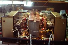
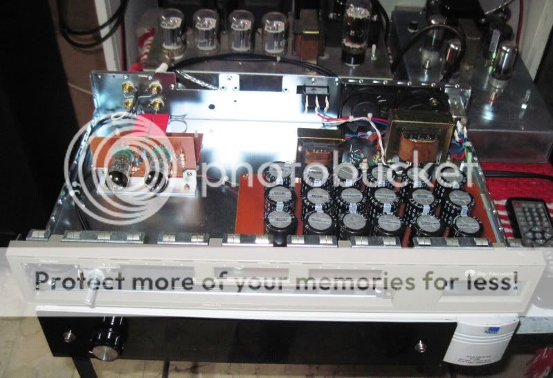
Here's the output side, the relays (2) one for on/off and one to bypass the resistors, each a 4 pole P&B with ~0.250" contacts in parallel, are on the other side of the stacked toroids. But you can see the cap bank.
Here's a link to a version of the same amp under construction, but using the 555 timer to control, and one of the relays (the resistor bypass relay) using a 2 pole rather than a 4 pole relay. The resistors are 50watt, iirc. I used higher power resistors in earlier versions where the control was manual, via a 3-position rotary front panel switch since you could forget to look at the changing color on the front panel display, and just run the amp in "start" mode. 😀 http://bearlabsusa.com/NEXT/SYMPHPS.jpg
Here's a link to a version of the same amp under construction, but using the 555 timer to control, and one of the relays (the resistor bypass relay) using a 2 pole rather than a 4 pole relay. The resistors are 50watt, iirc. I used higher power resistors in earlier versions where the control was manual, via a 3-position rotary front panel switch since you could forget to look at the changing color on the front panel display, and just run the amp in "start" mode. 😀 http://bearlabsusa.com/NEXT/SYMPHPS.jpg
Attachments
Having examined the relays on some high power amps after a few years of use and abuse i seriously wonder if these should not be considered "consumables". Yes, the big inrush current is taken by the resistors but there is plenty of evidence of arcing across the relay contacts. How good can this possibly be for the sound? I certainly hear power switches in the primaries, fuses and PC cords, so it does make sense that the relays would also be audible... and even more so after a couple of arcs.
Is an NTC better or worse?
Is an NTC better or worse?
In my case I have about 765J worth of energy to charge up on top of a 1.5kVa xformer on turn on 🙂
I used a regular soft start to start the transformer and then put simple slow charge circuit on after the xformer (before the diode bridge) to charge the cap bank.
The soft start relay kicks in full mains within 1/2 second or so, but the slow charge circuit is timed at close to 18secs before the relay kicks into full voltage! Also, depending on how the cap bank is configured (separate +ve and -ve rails) I split the charging duties so each side has less energy to charge up. In my case I just used a series of NTC's.
You need to also note what is connected behind the PSU. If you are connecting a Class A circuit behind all those caps, you need to take into account the constant current draw that the circuit demands on turn on.
That can not be over stated with this power level ! listen to him it will save you from a dangerous problem !For safety reasons, seriously high power PSUs should only be built by people who really know what they are doing. The necessary safety features add significantly to the cost and complexity of the PSU, so others will be tempted to omit them or not even realise that they are necessary.

not to forget that the reason we use soft start
is so that the mains switch do not weld on turn on,
and that our house lights do not dim nor trip circuit breakers...
a 10hm resistor will charge a 0.5F capacitor in about 20 secs,
a 100ohm in about 200 secs...
assuming a mains of 120 volts, and turn on at peak ac, current is 12 amperes,
more if the turn on occurred at zero crossing, so you need a power switch that
can handle at least 16 amps...
this is how i will approach this problem...
Wow.
You know, they make capacitance multipliers for a reason.
i have resisted the use of such CM in all of my amp builds,
i believe that having another amp in my amp is cheating,
but that is only me....😀
It surprising how often people go over the top with smoothing.
It usually creates more problems than it solves.
I designed a irs2092 class d amplifier.
I used 20,000uf per rail and the amp on power down squealed, popped, thumped and made siren type noises !
I went through my design with a fine toothcomb but couldn't find out why it did that.
I tried holding the chip in reset on power down and that fixed it.
The 2092 wasn't happy with very slowly discharging power supplies.
I got in touch with IR and they suggested a simple reset circuit that held the 2092 in reset when the VCC dropped below 12 volts.
I came up with a PIC micro based circuit with a2d on the PIC that looked at VCC.
When it dropped too low it reset the 2092 via an opto coupler.
Worked a treat.
An externally hosted image should be here but it was not working when we last tested it.
there are crazy folks out there like me...😀
the owner of this line amp was all smiles when i gave him this,
all according to his requests.....
18 x 470ufd filter caps for a circuit that is drawing not more than 20mA.....😱
i did not even use a soft start ckt as the impedance of the power traffo was
more than enough to take care of the inrush...
Analog_sa, I agree switch contacts are problematic.
That's why I used relays with over-rated contacts, and used multiple contacts in parallel to minimize the long term potential for problems. Generally I try to stay away from single contact relays or even switches.
_-_-bear
That's why I used relays with over-rated contacts, and used multiple contacts in parallel to minimize the long term potential for problems. Generally I try to stay away from single contact relays or even switches.
_-_-bear
Why not first short circuit relay contacts using a SCR and after that to do the relay ON?
In this way the relay terminals will be at a maximum potential difference of 1.5-2V and the relay contacts will be less stressed.
In this way the relay terminals will be at a maximum potential difference of 1.5-2V and the relay contacts will be less stressed.
Man I like your concept of using a resistor to handle the inrush currents but can you share the schematic how its done? to be more clear about it... it helps to understand precisely.. 🙂NTC = not such a good idea.
I use a series resistor shunted by a big relay. You can manually control the relay with a two position switch or use a timing circuit. I've done both.
If you use the former, be sure to use LARGE wattage power resistors, since you could, might just forget to flip the switch. It's been done. 😀
The 10 ohm value is about right - you can test and figure it out empirically.
I used ~500,000ufd total at about 60vdc in my Symphony No.1 Amplifier.
_-_-
the amplifier is of course for class H high power or Grounded bridge with MJE transistors.
Sorry I mistyped its 1,00,000uf per rail not 1F but the design to be rugged enough so that it can even accommodate the 1F per rail cap..!!!!
Sorry I mistyped its 1,00,000uf per rail not 1F but the design to be rugged enough so that it can even accommodate the 1F per rail cap..!!!!
the start up current flows through the current limiting NTC or resistors.
The relay sees nothing of this.
After an apprpriate delay the relay closes to short out the limiter. The load/transformer sees a slight increase in supply voltage and this gives a small increase in relay contact current cf the transformer quiescent current.
During the "start up" the stress applied to the relay contacts is insignificant.
During power OFF, activated by opening the Main ON/OFF switch, or when power fails, the relay contacts remain closed. Again there is no stress on the contacts.
OFF is the potentially damaging action that burns/welds switching contacts, but the soft start relay is NOT exposed to this.
A relay with contacts rated for the "normal transformer current draw" are entirely adequate.
a 300VA operating on 110/120Vac would have a normal current not exceeding 3A. A 4Aac or 5Aac relay is adequate for soft starting duty.
The Main ON/OFF switch is very different. It may need a 10Aac to 15Aac rating to give an extended life.
On 220/240Vac supplies those typical required current ratings are halved.
Infact the current consumptions will be in the order of tens of amperes as much as 30Amps so there should be enough rugged psu handling system.
Infact I had a thought to use triple relays like use one relay just for the transformer and one after starting the transformer use for the capacitors bank 1 and 2 so two relays linked in series like triggering one after other what do you say about this idea?
Infact I had a thought to use triple relays like use one relay just for the transformer and one after starting the transformer use for the capacitors bank 1 and 2 so two relays linked in series like triggering one after other what do you say about this idea?
tell me one thing the inrush current is being calculated as what? so that we can be precise lets consider that the capacitors used here are .1F so if the ESR is 0.007 ohm and hence the t is calculated on RC time constant which gives us the amount of current that can be calculated as C=it. That gives the idea about how much currents are we dealing with?
did a simulation using psu designer 2 and figured out as
1. using a bridge25 with secondary voltage of the trafo being at 100V with source resistance of 10ohm
2. Cap as .1F and load resistance of 5kohm
The resultant current transient max is 12Amps at .5sec
1. using a bridge25 with secondary voltage of the trafo being at 100V with source resistance of 10ohm
2. Cap as .1F and load resistance of 5kohm
The resultant current transient max is 12Amps at .5sec
Don't try to charge one bank and then the next.
You can produce offsets that could prove "problematic", unless you are very careful.
0.1F = 100,000ufd. At least it was last week. 😀
The issue on inrush current is not so much the standard calculated draw, although that is important, but what happens at or near the "zero crossing point" when the amp is turned on. You get a random time that you throw the switch, you might just time it perfectly so that the AC line voltage is near zero, in which case the current drawn for a little bit of time is scary high. Assuming the PS looks like a very low Z load, then the current looks very high. Or at least that's what someone said to me once.
The circuit is just a series resistor with a timing circuit or a switch to control a relay to bypass the resistor after some time. The one shown earlier in this thread is fine. Good enough.
I disagree with AndrewT about the significance of the switches (relays) and switch (relays) contacts, but a whole lot depends on how many layers down you wish to peel the onion.
Walter Jung wrote a detailed construction article
in the Audio Magazine sometime in 1980,
i have scans of that article but i can not post it here due to IP issues....
he used a 10 ohm/ 50 watt Dale power resistor, a 555 timer and a relay...
soft starting circuit need not be overly complicated....
as generous as i am with psu filtering,
i am likewise generous with switches and relays....
i will use a relay rated for 15 amps contact,
you can use the same for 240 volt mains,
a dpst mains switch rated for 15 amps is what i will use...
in the Audio Magazine sometime in 1980,
i have scans of that article but i can not post it here due to IP issues....
he used a 10 ohm/ 50 watt Dale power resistor, a 555 timer and a relay...
soft starting circuit need not be overly complicated....
a 300VA operating on 110/120Vac would have a normal current not exceeding 3A. A 4Aac or 5Aac relay is adequate for soft starting duty.
The Main ON/OFF switch is very different. It may need a 10Aac to 15Aac rating to give an extended life.
as generous as i am with psu filtering,
i am likewise generous with switches and relays....
i will use a relay rated for 15 amps contact,
you can use the same for 240 volt mains,
a dpst mains switch rated for 15 amps is what i will use...
- Status
- Not open for further replies.
- Home
- Amplifiers
- Power Supplies
- inrush current limiters for 3.3kva and 1,000,000uf per rail capacitors?