Hi All,
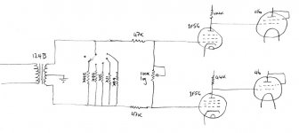
Been struggling with my very limited understanding of input/interstage transformers. In a setup I have with an input transformer (humble Hammond 124B-works surprisingly well and suits my 'budget') on the input to an amp should the volume pot be across the primary or secondary winding (between the grids of the diff pair)? The Tx is doing phase splitting to a pair of 1F5G's as diff amp driving trioded PP 46's sitting on a 6F6G CCS (local feedback from screen taps on output Tx to plate resistors of 1F5G's). Amp input is direct from CD player at present... Now would I just be better off to insert my 71A linestage (which has a volume pot across its input) and just do away with the pot on the amp? I'd really rather be able to use the amp without necessarily having to hook up the preamp just for volume control +/- impedance matching issues...
My understanding of the frequency concequences of primary/secondary loading and impedance matching etc is sketchy at best - I could really do with some help from the learned and experienced to set me off in a sensible direction. At present I have a 100K pot across the primary as one would for a standard SE voltage amp which works but the result is perhaps a bit on the 'bright' side (bass is fine) and in fairness I haven't explored the question of loading of the secondary or anything like that as yet.
Cheers, Andrew.
The volume control should be across the secondary. Take a look through the white papers on Jensen's site for some examples
www.jensentransformers.com
www.jensentransformers.com
Hi Andrew,
you and me both, mine is to do with output and PP plate load values operating point &etc another story,
But if you think about it volume pot should be ahead of transformer other wise I think it gets difficult trying to keep o/p stage ballanced you could come up with shunt arrangement or dual gang pot after transformer.
without knowing your exact arrangement my preference is pre the transformer, mind you the source z will change from the low volume to mid and high, but would have less effect than changing the output load z on the transformer secondary.
part of the fun i guess, with op-amps not a big issue just add another noise inducing NFB buffer stage.....
Robert
Hi Andrew,
Here is an example of a differential preamplifier with a couple of ways to implement the volume control.
http://www.raleighaudio.com/chapter_4.htm
Dave
Here is an example of a differential preamplifier with a couple of ways to implement the volume control.
http://www.raleighaudio.com/chapter_4.htm
Dave
Mmmm, 2 schools of thought with 2 to 1 in favour of pot across the secondary. Conceptually that is probably slightly more pleasing. The Raleigh Audio approach was what I was what I had in the back of my mind (nice to see it implemented by someone so at least I can be confident it will work)
SY - ta muchly for the ref to the Jensen site. Loads of info but mucho bewildering - could I trouble you to point out the more poignant papers to this Tx neophyte?
Presumably I will need to work out what resistance across the secondary sounds best (least ringing with these cheapo trannies) and then fashion a setup as in Fig 17 of the Raleigh Audio or pannos29 on this forum (that thread started after my search and I'm embarrassed to admit I didn't see it before my post....). Should I use my preamp (likely output impedance of perhaps 2K) in the chain with the current vol pot removed and then experiment until I get the sound I like or can I leave the pot across the primary for the time being and skip the preamp? Are the shunts across the primary and secondary likely to significantly interact or are the relatively independant? No sig gen/o-scope available so I can feel a bit of trial and error coming up!!
Cheers,
Andrew.
The maker of the input transformer will generally recommend a load. If your potentiometer is larger than the recommended load, you can either pad it down by paralleling a suitable resistor or use a series RC to tame any ringing. For the case of the Jensen JT11-P1, the recommended load is 10K; in my preamp (http://www.diyaudio.com/forums/showthread.php?s=&threadid=58757), I used a 100K volume control, then just paralleled the control with a 15K resistor to bring the load closer to spec. IIRC, Jensen showed the series RC trick on the JT11-P1 datasheet.
Putting the pot on the primary of an input transformer will compromise the common-mode rejection.
I'll poke around and see if Hammond specs the best-case load for your transformer.
Putting the pot on the primary of an input transformer will compromise the common-mode rejection.
I'll poke around and see if Hammond specs the best-case load for your transformer.
Thanx SY - a lot of the info I need. Ta for the link to your preamp schematic. May I ask is the 1M resistor from pot wiper to ground just insurance in case the wiper ceases wiping?
I will jump straight into loading the secondary of the Tx with the pot tonight after the kids are fed, washed and in bed...
Would it be wise to find a good value of total load resistance and then split it in 3 series parts with the central bit being the pot (I don't mind changing from 100K that's just a value I use from habit for volume pots) and equal to half the total needed load R? This is basically the schema used by the Raleigh Audio design for push-pull grids in a differential setup like mine (the SE case is way easier to get my brain around - as in the Heretical Unity Gain Line Stage).
Cheers, Andrew.
re: the raleigh audio page
In the second (single pot) volume control configuration, I think it's wired wrong. The pot should be wired across the two grids with the wiper to one of them. In other words, all three lugs are used, and then the secondary load doesn't change with the volume control setting.
I believe that's the way Morgan Jones does it in his book as well, or am I remembering this wrong?
Joel
Joel,
I think the method you mention in MJ's book requires a fully floating secondary, or source.
I think the method you mention in MJ's book requires a fully floating secondary, or source.
May I ask is the 1M resistor from pot wiper to ground just insurance in case the wiper ceases wiping?
Precisely.
I'll run through David's site later today and try to answer the second question unless he does first.
Hi Andrew,
Resistors placed across the primary and secondary will interact. Each is reflected across the transformer as the square of the winding ratio.
Sy is correct in that putting the potentiometer on the primary will compromise the common-mode rejection. One of the advantages of a transformer on the input is that it provides the opportunity of having a balanced input. Of course, you can ground one side of the primary and have an unbalanced input if you want. Putting the potentiometer across the primary forces an unbalanced input.
Determining the total load resistance and then splitting it into three (unequal) parts is a good way to start. The main reason for the shunt resistors is to provide a minimum input impedance when the volume control is turned all the way down. If they were not there, the input impedance would be zero Ohms when the volume control was turned down. Determine what you want your minimum input impedance to be and then each shunt resistor should be one-half that value.
The shunt volume control can be used with the center tap of the secondary of the input transformer either floating or grounded. With the center tap floating you will need to provide a ground reference to the grids with resistors between each grid and ground. These resistors are not needed if the center tap of the transformer is grounded.
The volume control configuration shown in figure 6.9 of Version 1 of Morgan Jones is essentially the same as that shown in configuration B of figure 17 in the Raleigh Audio article. In both cases the potentiometer is wired between the two grids with the wiper of the potentiometer connected to one of the grids. Raleigh Audio shows the top of the potentiometer floating and not used. Morgan Jones shows the wiper also connected to the top of the potentiometer, which shorts out that part of the potentiometer so it is not used. In both cases the input impedance will vary with the setting of the potentiometer.
Dave
David Davenport said:The main reason for the shunt resistors is to provide a minimum input impedance when the volume control is turned all the way down. If they were not there, the input impedance would be zero Ohms when the volume control was turned down. Determine what you want your minimum input impedance to be and then each shunt resistor should be one-half that value.
Don't you mean series resistors instead of shunt resistors?
se
Steve Eddy said:
Don't you mean series resistors instead of shunt resistors?
se
Yes of course, sorry for the confusion.
Dave
David Davenport said:Yes of course, sorry for the confusion.
Thanks, Dave. No problem. Just wanted to make sure I was looking at the right schematic. 🙂
se
I need to ask a heretical question here - kept me awake last night thinking about it. My DAC digital board has a balanced output straight into a valve stage(SRPP), so the volume control is at the end of the valve stage. Right now this feeds the input stage of the amp. So two coupling caps - before the volume control in the DAC-pre, and before the output stage of the amp. But I really have one stage too many here. It strikes me I can get rid of one stage and one coupling cap if I direct couple two stages out of the DAC digital section by using two diff pairs. This gives me enough gain to drive the output stage. But this means putting the volume control right before the output stage. I've never seen this in practice - what are the drawbacks of putting the volume control later in the amp? I can use a stepped attenuator with 1 watt resistors so that's not a problem, so what other reasons are there for not adopting this topology? I'm rather seduced by the idea of only one coupling cap in the whole chain. Since these are my amps, I don't care about industry protocol, I just want to know if it's worth building, and any tips on how to implement it. Thanks, guys. Andy Evans
Whilst I wouldn't disagree with any of the theory that shows the pot across the secondary... I regularly try both out and so far have always found it sounds better before the primary. Yes I know it's wrong according to theory but it sounds better in my amps and my system...
Not wanting to provoke a debate - just offering a differing account.
James
Not wanting to provoke a debate - just offering a differing account.
James
oh dear,
my thoughts also I somehow thought the cd out would have been unbalanced in the first place anyhow, (but I need to break that mind set don't I,..) My preference and this would be if it were the case that the source was unbalanced to feed signal hot to the top of the pot and wiper com to the transformer. thanx for the link SY re balanced audio interesting stuff.
Robert
Hi All,
Finally had a chance to fashion a volume control on the secondary side of the tranny. Rotary switch with a series of shunting R's to give variable loads. Been listening to 100K mostly which sounds quite good - fuller bass and less tizzy top end than the pot across the primary. 200K is a bit thinner but I really can't pick much in the way of difference with loads from 100K down to 6K. This is with the input straight from DVD and I guess may not be so with a preamp in the chain (my current one has an output impedance of around 2K).
Is it a reasonable rule of thumb to use the secondary load roughly equal to the rated secondary impedance? So for a 10K:90K (like mine) 90K would be good and for a 10K:10K then 10K would be a good place to start?
Cheers and thanks for all the help, much appreciated.
Andrew.
Attachments
Square test
Apart from the listening test which is very much needed indeed, I would suggest you to try square wave test at about 3-10KHz signal while changing the secondary loading in order to get the best results. I my case it worked wonders and completely transformed the responce of the input transformer, in my case 10K was the best ans 6K and 22K was acceptable.
Regards,
Panos
- Status
- Not open for further replies.
- Home
- Amplifiers
- Tubes / Valves
- Input transformer & volume pot