Why amplifier designer has to put resistor input normally 1K ohm after RCA-In.
What are the purpose of that resistor?
Can I put capacitor 2.7nF after 1K ohme to ground? (low pass filter of 58946.275 Hz)
My amp does not have that 2.7nF capacitor after resistor 1 Kohms.
What are the purpose of that resistor?
Can I put capacitor 2.7nF after 1K ohme to ground? (low pass filter of 58946.275 Hz)
My amp does not have that 2.7nF capacitor after resistor 1 Kohms.
Attachments
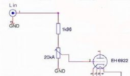
Preventing RF from entering the amp is a good cause and there's not much reason not to do this. The resistor might also help by linearising the source impedance.
Can I insert 2.7uF capacitor next to 1K ohm resistor and put another wire of capacitor to ground? So I get low pass filter
Yes.Can I insert 2.7uF capacitor next to 1K ohm resistor and put another wire of capacitor to ground? So I get low pass filter
Last edited:
Why amplifier designer has to put resistor input normally 1K ohm after RCA-In.
I would insert the resistor in series with the grid.
How I see it :
iImagine that
- the cursor is either full clockwise or full anti-clockwise,
- the grid connection from the pot cursor is slightly inductive,
- there are parasitic capacitors
between the cathode and the grid and
between the anode and the grid.
That's a lawn propitious for LC oscillations.
The purpose of a resistor in series with the grid is to damp them.
to eradicate frequency above 58,946.275 Hz.
So frequency below 58,946.275hz can pass into amp. even 20000-58,946.275 can't be hear.
But to preserve the phase not to change within -30db between 10000-20000 hz
So frequency below 58,946.275hz can pass into amp. even 20000-58,946.275 can't be hear.
But to preserve the phase not to change within -30db between 10000-20000 hz
Should always be on the grid pin to gain maximum benefit against the possibility of oscillation.
In the original picture you are only getting part of its potential benefit.
Shoog
In the original picture you are only getting part of its potential benefit.
Shoog
Putting a resistor as shown above the volume pot does almost nothing. It needs to go straight onto the grid pin.
Adding a 2.7nF (not uF!) capacitor to ground might make the input difficult to drive. Note that the HF rolloff is extremely unlikely to be at 58,946.275Hz. Several reasons for this:
1. resistors are not usually obtainable at such tight tolerance
2. capacitors are perhaps never obtainable at such tight tolerance
3. the source impedance affects the result
Might be better to describe the rolloff as being at 59kHz or even 60kHz. Have you heard of significant figures?
- Status
- Not open for further replies.
- Home
- Amplifiers
- Tubes / Valves
- Input resistor (What are purposes?)