If we put 20 k and in theory the Zout is zero ohm and Xc is zero ohm
And Zin of amp is infinity
The real load seen is 5 kohm. 10k//10k at 50 % of the pot (-6 dB)
In Audioreview one test of preamp is to check the freq answer at max volume and -6dB
When the coupling is not perfect is possible to see a narrow response on frequency
Mainly in tube stuff.
Due coupling caps or Cin too high
My understanding of the 1:10 rule of thumb is that it describes the ideal minimum relationship between output impedance of the preamp and the input impedance of the amp but that a higher ratio is OK.The 1:10 rule of thumb.
However, earlier in the thread the designer posted a link to a discussion of the volume control being on the output. In it he mentions 1:4 rule of thumb, or maybe he expresses it as 4:1. I had never heard that ratio mentioned elsewhere. So I took it to mean that, while possibly not ideal, it was something he considered acceptable or perhaps the maximum ratio. Of course I later learned that all the calculations in that link referred to a different preamp design. So perhaps the 1:4 rule of thumb also doesn't apply to this design either??
For an amp with a 10k input impedance, anything under 1k would be ideal. And perhaps anything under 2.5k would be considered acceptable??
The output impedance of the CF is supposedly 612 ohms. How is that affected by the use of a combination of a 10k pot and 1uf cap (the stock combo) vs a 10k pot and 10uf cap vs a 100k pot and 5uf cap?
I hate to ask but, is there a formula?
You are welcome. The preamp’s output amplifier (a cathode follower in this case) output impedance does play a role as you correctly heard. It’s just that the the value of that impedance is usually very small relative to the load resistance which it drives that it typically becomes negligible. For demonstration using your example of a CF with a 612 ohm output impedance, you would simply sum that impedance with whatever value is the load in series with it. In other words, you can treat it as though it were a fixed value part of the upper segment of the volume pot.OK, so I think I'm getting it now. Thanks so much!!
So the output impedance of the CF (612 ohms) doesn't really figure into the calculation? He seemed to indicate that it did.
For example: [612 ohms + 9K ohms upper-segment of pot. + (1K || 10K = 909 ohms) = 10,521 ohms in total]. 10,521 ohms in conjunction with a 1uF coupling capacitor gives a -3dB frequency of 15Hz. When we didn’t consider the effect of the CF output impedance, the total load was 9,909 ohms, only a 6% difference. Which is why the -3dB frequency only changed by 1Hz.
You can see why it’s often considered better (but not always, for reasons of noise, and input bias current offset) to have the power amplifier’s input impedance higher than lower. As doing so enables the use of a smaller value (read as, less costly) coupling capacitor.
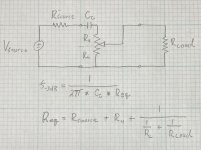
I will try to make this as simple as possible. In figuring the low frequency rolloff point you need to include the source impedance, the coupling capacitance, both sections of the volume control (above and below the wiper contact), and the load impedance on the circuit. Please look at the attached diagram.You've posted the results in chart form but not the actual calculation. What formula is used to integrate effect of the CF impedance and the series R of the pot with the data points (the 1uf cap and the various R to ground values) used by the high pass calculator? If you could "show your work" rather than just the answers it would help.
First, please note from the equation for the frequency, that the lower Req becomes (for a given value of Cc) the greater the rolloff frequency will become. When Rl is small compared to Rload, then Req is relatively constant and that accounts for the "flat" part of the curve on the left hand side of the graph. However as Rl gets larger and Ru gets smaller, the total resistance will become smaller because the Rload is in parallel with ever greater portions of the volume control total resistance. This is why the curves bend up at large values of control setting.
Given the numbers I used Rsource = 612Ω, Cc=1.0µf, Ru+Rl= 10kΩ, and Rload = 10kΩ. So at 50% shaft setting on an audio taper potentiometer, RL≈1kΩ and Ru ≈9kΩ. This makes Req=612+9000Ω+909Ω=10.52kΩ. But at 100% shaft setting, Req = 612Ω+10kΩ||10kΩ=5612Ω. Because Req is smaller, the low frequency cutoff is higher.
Does this help clear up your confusion?
Attachments
The 4:1 rule (the rule I learned for matching networks back in Engineering school and which I used for 33 years as an Electrical Engineer) for port to port impedance matching is based on an allowable 2dB of loss in the port matching. This is a reasonable amount of margin to build in for cascaded networks in reconfigurable systems. So if the source impedance is 1 and the load impedance is 4 (or any multiples thereof), then the voltage transferred is 4/(1+4)=0.8. Then 20*log(0.8) = -1.94dB ≈ -2dB.My understanding of the 1:10 rule of thumb is that it describes the ideal minimum relationship between output impedance of the preamp and the input impedance of the amp but that a higher ratio is OK.
However, earlier in the thread the designer posted a link to a discussion of the volume control being on the output. In it he mentions 1:4 rule of thumb, or maybe he expresses it as 4:1. I had never heard that ratio mentioned elsewhere. So I took it to mean that, while possibly not ideal, it was something he considered acceptable or perhaps the maximum ratio. Of course I later learned that all the calculations in that link referred to a different preamp design. So perhaps the 1:4 rule of thumb also doesn't apply to this design either??
A 10:1 rule (which I have only ever heard from internet forums and not any Engineering classes I ever took) would result in a voltage transfer of 10/11≈0.91. Then 20*log(0.91) = -0.83dB. This is technically better but only by 1.1dB.
Going to such great lengths to obtain a 1.1dB improvement in cascaded stages is (if you'll pardon my professional assessment) silly. Especially when we are dealing with signals having dynamic ranges of 40dB or more.
So many words and theory while there is a device with wrong values probably chosen empirically 😀
Great lengths!?! One picks the standard and most easy to obtain/find value 10 kOhm and designs/picks/matches amplifiers that are 100 kOhm or higher which happens to be a more or less automagically occurring feature of most.
So it seems in the tube world many go into great lengths to do it completely against any calculation/rule of thumb or even simple logic. This whole preamp business in times that no one ever needs a high gain preamp is a silly habit creating more issues than it solves and filling many threads. It is audio self mutilation.
Last edited:

@jean-paul, even worse when the discussion is about output transformers. Zillions of (approximate) calculations and lots of speculation without any experiment.😆
Hi, Suncalc,The 4:1 rule (the rule I learned for matching networks back in Engineering school and which I used for 33 years as an Electrical Engineer) for port to port impedance matching is based on an allowable 2dB of loss in the port matching. This is a reasonable amount of margin to build in for cascaded networks in reconfigurable systems. So if the source impedance is 1 and the load impedance is 4 (or any multiples thereof), then the voltage transferred is 4/(1+4)=0.8. Then 20*log(0.8) = -1.94dB ≈ -2dB.
A 10:1 rule (which I have only ever heard from internet forums and not any Engineering classes I ever took) would result in a voltage transfer of 10/11≈0.91. Then 20*log(0.91) = -0.83dB. This is technically better but only by 1.1dB.
Going to such great lengths to obtain a 1.1dB improvement in cascaded stages is (if you'll pardon my professional assessment) silly. Especially when we are dealing with signals having dynamic ranges of 40dB or more.
Rules of 10 are what Americans often refer to as, 'rules-of-thumb'. Meaning, value approximations which are quasi-arbitrary, but yet close enough to optimum for use in practical applications which are not critical. Such as, audio. Which also means that they really aren't rules, not in the 'must be followed' sense. Quasi-arbitrary ratios of 10 are merely easier for human beings to consistently remember than are other such ratios, even if those other ratios are closer to being 'theoretically' optimum.
Another ratio of 10, rule-of-thumb related to this thread discussion is the determination of the output coupling capacitor value. After calculation of the desired -3dB high-pass roll-off frequency, the actual value of the capacitor is typically chosen as 10 times that calculated for the desired -3dB limit. For example, if the signal channel FR is desired to be largely flat down to 20Hz, then the -3dB is first calculated for 20Hz. Then the actual value of the selected capacitor is then chosen to be 10 times greater, thereby moving the -3dB frequency a decade lower to 2Hz in order to more flatten the response at 20Hz. Or, to simply calculate the cap. value which is necessary to produce a -3dB frequency that is 10 times lower that the desired flat response limit of the signal channel. So, calculate the -3dB cap. at 2Hz, instead of at 20Hz.
Last edited:
Except that leads to severe blocking distortion in momentary overdrive conditions. Who would do such a thing?Another ratio of 10, rule-of-thumb related to this thread discussion is the determination of the output coupling capacitor value. After calculation of the desired -3dB high-pass roll-off frequency, the actual value of the capacitor is typically chosen as 10 times that calculated for the desired -3dB limit. For example, if the signal channel FR is desired to be largely flat down to 20Hz, then the -3dB is first calculated for 20Hz. Then the actual value of the selected capacitor is then chosen to be 10 times greater, thereby moving the -3dB frequency a decade lower to 2Hz in order to more flatten the response at 20Hz. Or, to simply calculate the cap. value which is necessary to produce a -3dB frequency that is 10 times lower that the desired flat response limit of the signal channel. So, calculate the -3dB cap. at 2Hz, instead of at 20Hz.
I'm done. You can lead a horse to water...
I have ready my preamp with same configuration, gain + CF
I will change the pot position and value and output cap
Then I will measure
After 30 April.
As usual too many words ( and also simulation)
Walter
I will change the pot position and value and output cap
Then I will measure
After 30 April.
As usual too many words ( and also simulation)
Walter
You might want to have both input and output level controls, just to see how much intermodulation distortion is "correct".
All good fortune,
Chris
All good fortune,
Chris
Yes I add the one in output and leave the old in input as usual
No reason to put the volume on output
Think about a power amp with separate input level
There is a pot of the pot
😉
Walter
No reason to put the volume on output
Think about a power amp with separate input level
There is a pot of the pot
😉
Walter
I do not at all understand your oddly emotional and dismissive reaction. I'll just leave it at that.Except that leads to severe blocking distortion in momentary overdrive conditions. Who would do such a thing?
I'm done. You can lead a horse to water...
Never seen blocking in thousands of tube preamp I have checked/tested and some built
Probably the blocking could be the stop of your considerations
Probably the blocking could be the stop of your considerations
Yes, thanks, this confirms Ken's earlier explanation. As I said, I ran the high pass calculator with data based on settings at 10%, 50%, 70% and 100% and the results tracked your graph results.I will try to make this as simple as possible. . . . Does this help clear up your confusion?
Thanks again. That's a very helpful and understandable explanation. I've always wondered how deviation from the the 1:10 rule of thumb affects the results and this quantifies it.The 4:1 rule (the rule I learned for matching networks back in Engineering school and which I used for 33 years as an Electrical Engineer) for port to port impedance matching is based on an allowable 2dB of loss in the port matching. This is a reasonable amount of margin to build in for cascaded networks in reconfigurable systems. So if the source impedance is 1 and the load impedance is 4 (or any multiples thereof), then the voltage transferred is 4/(1+4)=0.8. Then 20*log(0.8) = -1.94dB ≈ -2dB.
A 10:1 rule (which I have only ever heard from internet forums and not any Engineering classes I ever took) would result in a voltage transfer of 10/11≈0.91. Then 20*log(0.91) = -0.83dB. This is technically better but only by 1.1dB.
Going to such great lengths to obtain a 1.1dB improvement in cascaded stages is (if you'll pardon my professional assessment) silly. Especially when we are dealing with signals having dynamic ranges of 40dB or more.
Many people use tube preamps whose output impedance does not conform to the 1:10 ideal when used with their SS and Class D amps. As I said earlier, the owners of such amps seem to account for much of the current popularity of tube preamps.
Despite this, they enjoy the result. And I've had similar experiences, I also prefer the sound of Class D with tube preamps. That said, I still find an all tube system to be much more enjoyable. That's just my preference.
So while the difference between impedance ratios can be calculated and, no doubt, measured, it may not be audibly obvious if someone isn't doing an A-B critical listening test. They would be unlikely to hit play and recognize that there is some deficiency in the audio quality. So it would not necessarliy affect their enjoyment when casually listening to music. And even if they did an A-B critical listening test, they might not be able to tell much difference, if any.
Again, please correct me if I'm misunderstanding this . . . . I've been under the impression that the reason that the -3db point is often set so far under 20Hz is that phase anomalies may be present at frequencies up to 10x the -3db rolloff point.For example, if the signal channel FR is desired to be largely flat down to 20Hz, then the -3dB is first calculated for 20Hz. Then the actual value of the selected capacitor is then chosen to be 10 times greater, thereby moving the -3dB frequency a decade lower to 2Hz in order to more flatten the response at 20Hz. Or, to simply calculate the cap. value which is necessary to produce a -3dB frequency that is 10 times lower that the desired flat response limit of the signal channel. So, calculate the -3dB cap. at 2Hz, instead of at 20Hz.
That said, I've set the rolloff point higher when using a small output transformer in order to reduce the possibility of saturation that might occur if the rolloff point was lower. The result sounded fine, which makes me wonder about how audible such phase anomalies might be with music playing.
In the example of the preamp being discussed, if the -3db point is at 16Hz, doesn't that mean that the fundamental is flat down to 32Hz? BTW, 31Hz is the lowest note on a 5 string bass guitar and it's 40Hz for a more traditional 4 string bass. And many speakers don't play that low anyway.
So, purely from a listening perspective, the importance of a -3db point of 2Hz depends on the audibility of whatever phase anomalies might be present, not so much on the ability to reproduce the fundamental or to ensure that the overall frequency response is adequate.
Obviously, setting it lower would still be better from a technical perspective.
I'm maybe wrongly assuming most people will be using this with a DAC or some sort of streamer, you can then control the output of those devices to play with this relationship.You might want to have both input and output level controls, just to see how much intermodulation distortion is "correct".
All good fortune,
Chris
True. But if that's the case there is also no need for a volume control on the output either.I'm maybe wrongly assuming most people will be using this with a DAC or some sort of streamer, you can then control the output of those devices to play with this relationship.
A physical control is only needed if the user has no other means of adjusting the volume. If that's the case, I see two possible advantages of using pots on both input and output.
First, the input pot can reduce the signal if it's too hot which, I admit, may be an unlikely scenario. Second, and potentially more useful, is that it can also be used to adjust the amount of "color" if such "color" is affected by the strength of the incoming signal. And, if the user finds that no adjustment is needed, the pot can simply be turned wide open.
Another option, which is what I did, is to use a pair of mono pots on one end or the other. This allows the L-R balance to be adjusted, which some people might find useful if their listening position is not always centered between the speakers.
As I see it, such a configuration offers maximum versatility without having any significant negative impact sonically, assuming that good quality parts are used.
"True. But if that's the case there is also no need for a volume control on the output either."
The reason for the volume control on the output has been explained ad nauseum and that controlling the input via the DAC/streamer output (or a pot) performs a different function has also been explained, which you noted.
My point was there is no reason to put a volume control on the input to "control the amount of color" if the DAC/streamer has an output control, as it will provide attenuation to the strength of the input signal, exactly like a pot would do. Obviously if the source has no output control, that wouldn't be the case.
- Home
- Amplifiers
- Tubes / Valves
- Input or Output Pre-amp Volume Control