...
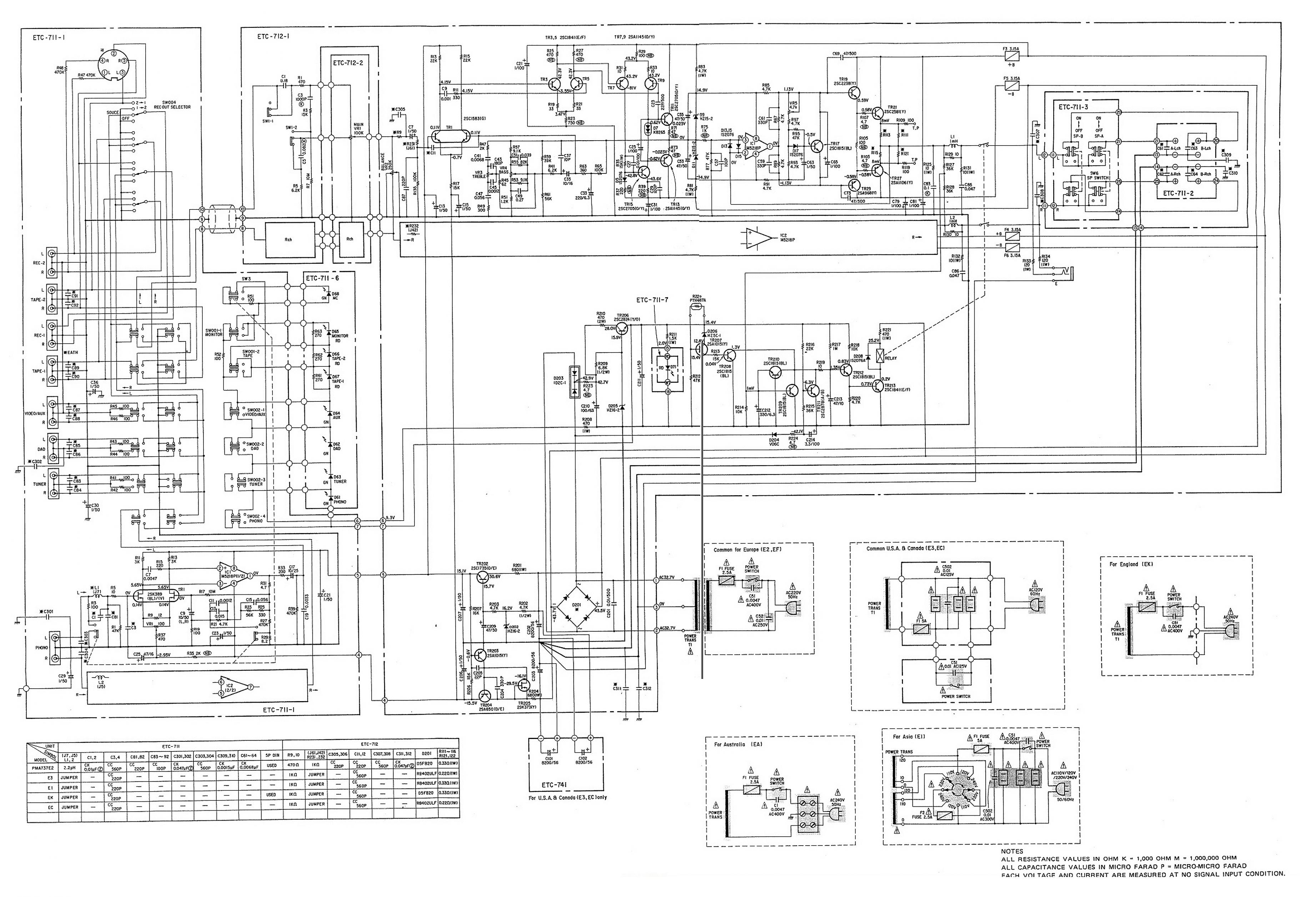
BTW, please post a big picture of the whole amp board circuit diagram so we can check it out.
This is the biggest I could get.
Attachments

In my most recent project, I used a X5R, 100uF/6.3V MLCC ceramic from Nic Components for input DC blocking.
These things do have a bit of a voltage coefficient, but I've tested it on the AP System Two at work and it doesn't look any different from a piece of wire. Wether you can actually *hear* this cap is subject to a few debates/flames/etc though 😀
Interesting, but it makes sense. Assuming an input impedance of 47k, you've got a break point at 34mHz (yes milli) using this cap, and since this type of capacitor is well known to have very low ESR (typically used for power decoupling) then it is unfeasible that any audio frequency will impose any voltage across it. So, in essence, at AC it really is like a piece of wire! Something worth bearing in mind for any coupling capacitor; if it's oversized and low ESR then how can it add any distortion!? 😀 . Effectiveness at DC blocking is debatable though, it will still pass some potentially damaging low frequencies in this scenario.
This is the biggest I could get.
Now it can be seen. Your true input cap is C7. What value is C305?
I disagree.
Ceramics are made in many different types for many different duties.
For some duties, the correctly selected ceramic, cannot be improved upon.
This was just in reference to their audio quality, X7R and Z5U for example, are very poor by comparison for audio.
C305 is 220pF 5% 50V, ceramic.Now it can be seen. Your true input cap is C7. What value is C305?
Karl, besides the caps you already removed (the ones marked red in your previous post) I'd remove C305, eventually also C87 (carry out a listening test after each mod), and increase C7's value replacing it with no more than 10uf.
Remember that those are at the left channel and you have to take care of the right ones as well.
Search for RF using an oscilloscope at 8, 9, and 10 at the interconnect between boards 711 and 712. You should have the amplifier interconnected to the preamp or any other module you are using as source, have them ON with no signal (just idling). If you don't find RF there then all is fine (I bet you won't find any RF)
I recommend X7R for audio amplifiers/pre-amps/RIAA amps/Buffers regularly.This was just in reference to their audio quality, X7R and Z5U for example, are very poor by comparison for audio.
They are difficult to beat when used for the correct duty.
There are many who agree.
I recommend you keep C305 and C87................ I'd remove C305, eventually also C87 (carry out a listening test after each mod), ..............
They are your RF attenuation at the amp input.
Karl, besides the caps you already removed (the ones marked red in your previous post) I'd remove C305, eventually also C87 (carry out a listening test after each mod), and increase C7's value replacing it with no more than 10uf.
Remember that those are at the left channel and you have to take care of the right ones as well.
...
Hi Pablo,
Original C7 was a 1uF 50V electrolytic and, during the recap of the amp, I replaced it with a 1uF 63V polypropylene. If I increase C7's value to max 10uF, I have to use an electrolytic. That's not a problem.
C87 and C88 (post #76) were the only two I removed so far (for RF bypass at VIDEO/AUX connectors).
One question: if I have to put C87 and C88 back, are ceramics most suitable for RF bypass? Or I can use other type of cap for this purpose?
Thanks. 🙂
Karl, yes, C7 should be electrolytic. Regarding C305 and C87 I meant the caps in board 712 next to C7 (it's strange why they use the same labeling for components in different locations.
Remember as said above, to modify the right channel as well!
If you were to put the caps back may be you just use the same you removed, but in any case if you want to replace them ceramics would be fine.
I agree with Andrew that all those caps mentioned (except for C7) are for RF control, but many times they are overkill and do have an impact on sound since they are in the signal path.
I do strongly recommend not removing those in the input connectors negative side to ground though.
I recommend X7R for audio amplifiers/pre-amps/RIAA amps/Buffers regularly.
They are difficult to beat when used for the correct duty.
There are many who agree.
Hi Andrew, for which duty do you advice X7R, local decoupling ?
Regards
Karl, yes, C7 should be electrolytic. Regarding C305 and C87 I meant the caps in board 712 next to C7 (it's strange why they use the same labeling for components in different locations.
Remember as said above, to modify the right channel as well!
If you were to put the caps back may be you just use the same you removed, but in any case if you want to replace them ceramics would be fine.
I agree with Andrew that all those caps mentioned (except for C7) are for RF control, but many times they are overkill and do have an impact on sound since they are in the signal path.
Okay, here are the two input caps C7 (left ch.) and C8 (right ch.) in board 712 to replace with a value to max 10uF.
And C87, C88 to possibly be removed after some tests. C305 and C304 (not shown here), too.
An externally hosted image should be here but it was not working when we last tested it.
I'll do it in the next days and will report back. Thanks!
P.S.: Any further tweaks/improvements on board 712 will be welcome.
Okay, here are the two input caps
I'll do it in the next days and will report back. Thanks!
P.S.: Any further tweaks/improvements on board 712 will be welcome.
Cool; try this out first and report back.
thanks for the great recommendation!
thanks for pointing at it!
good thing it has a 2015 edition, too! (the 3rd)
(...)
I recommend you get a copy of Horowitz & Hill Art of Electronics ...
thanks for pointing at it!
good thing it has a 2015 edition, too! (the 3rd)
- Status
- Not open for further replies.
- Home
- Amplifiers
- Solid State
- Input capacitor