It doesn't work well - this gets you a permanent 50:50 pickup mix. If the mix pot has far less resistance than the load, it doesn't attenuate either pickup output, no matter where it's set, so it's almost the same as just wiring the two pickups in parallel directly.Leaving the balance pot, but eliminating the volume control - and saving the 10M input, what does that do to the simulation?
I tried replacing the 500k volume pot with a 10M pot and simulating that, and sure enough, there is barely any mix range, only about 0.1 dB.
It would be really helpful to know the series capacitance of these pickups. Without that, we're all shooting in the dark as far as bass response goes.
-Gnobuddy
I just tried measuring capacitance using my fluke 87V. not sure how accurate that is though. This isn't a measurement I do very often.
I got 7.5nF (0.75 x 10nF) for single sensor and 13nF (1.3 x 10nF) for the two in parallel.
The cases probably add capacitance too.
I got 7.5nF (0.75 x 10nF) for single sensor and 13nF (1.3 x 10nF) for the two in parallel.
The cases probably add capacitance too.
If this is true, the capacitance will be much less than a flat disc. The biggest-value pots we can buy these days are 1M, and if the pickup capacitance is too low to work with these, then your only choice is to use fixed-value resistors (chosen to tweak the pickup balance to suit your preference.)...a thick crystal...instead of a flat disk piezo.
Your other comment that using an input impedance between 1M and 10M varied the bass response is also of some concern. With a 10nF or more piezo disc, there is still full bass response below 40 Hz even with a 1M input impedance, so you won't hear any bass change in reducing the pickup input impedance from 10M to 1M.
(However, really low frequency thumps and bumps - the sort produced by your hands on the instrument - will be removed, even with a 10nF or more pickup, by reducing input impedance to 1M. Perhaps that's what the musicians who tried this heard?)
So, in short, we don't know. And we're really working entirely blind until you know the capacitance of the pickups. 🙁
Is it possible to contact the pickup manufacturer and get a straight answer as to the source capacitance of their pickup?
My gut instinct says that all that's in that expensive-looking pickup enclosure is a generic ten-cent piezo disc. Add the metal housings and wire bits, and apparently that goes up to $784 Canadian dollars.
 But a gut instinct isn't a reliable starting point for an engineering design!
There are quite inexpensive DMMs (meters) that can measure capacitance these days, and with one of these, you can measure your piezo capacity directly. If the manufacturer isn't forthcoming, AND you can't easily open up one of the sensor housings to see what's inside, this might be an alternative.
There is a third alternative too - if you can build fairly simple electronics circuits, it isn't hard to work around all of these problems. A couple of JFETs and a few resistors will let you solve the entire problem.
-Gnobuddy
Interesting...and lower than I expected. Was this with DMM cables or the sensor cable also included?Fluke 87V...7.5nF (0.75 x 10nF) for single sensor and 13nF (1.3 x 10nF) for the two in parallel.
It might be worth trying a two stage measurement, first measure capacitance with all cabling, but NOT plugged into the piezo. Then plug in the piezo and make a second measurement. In a perfect world the difference would be the sensor capacitance. In the real world, we might get a slightly better idea.
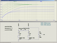
But 7.5 nF is already useful...I plugged that value into the LTSpice simulation, and with both pots (mix and volume) increased to 1 Meg, things look usable - screenshot attached.
Incidentally, there are smaller-diameter ten-cent piezo discs, some of which have capacitance in the right ballpark (7.5 nF). Being smaller, they also have no mechanical resonances in the bass guitar frequency band, so they will provide a flatter frequency response and a more neutral sound.
-Gnobuddy
Attachments
Interesting...and lower than I expected. Was this with DMM cables or the sensor cable also included?
-Gnobuddy
The .75 measurement was just one sensor without any cabling attached.
the 1.3 measurement was with the "bridge" cable connecting both pickups in parallel. The output cable was removed for the measurement.
The DMM measurements were a little noisy but I think these are pretty close measurements. I didn't remove the sensors from the bass - that's a project in itself. So I'm sure any noise and bumping were affecting the readings.
Sounds good!The .75 measurement was just one sensor without any cabling attached.
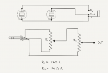
Well, it looks like the circuit Enzo suggested will work, with a couple of 1M pots, or one 1M linear "Mix" pot, and one fixed 1M resistor, if you don't need to turn down the piezo signal.
There isn't a huge amount of mix range, but hopefully sufficient for your purposes. The only way to get more mix range is to also increase signal loss (insertion loss), by reducing the resistance of the "Volume" pot, so the goal is probably to have just enough mix range for your preferences.
Incidentally, I'm always amazed that anybody is able to play upright bass - it seems such a difficult instrument to a person like me, spoiled by guitars with frets and low action and manageable scale lengths. My hat is off to you, and every other upright bass player!
-Gnobuddy
Sounds good!
Well, it looks like the circuit Enzo suggested will work, with a couple of 1M pots, or one 1M linear "Mix" pot, and one fixed 1M resistor, if you don't need to turn down the piezo signal.
There isn't a huge amount of mix range, but hopefully sufficient for your purposes. The only way to get more mix range is to also increase signal loss (insertion loss), by reducing the resistance of the "Volume" pot, so the goal is probably to have just enough mix range for your preferences.
-Gnobuddy
I have a custom "stereo" cable that assuming I got the concept right, means I could have the resistor circuit hidden in the tailpiece of the bass (see attached)
Incidentally, I'm always amazed that anybody is able to play upright bass - it seems such a difficult instrument to a person like me, spoiled by guitars with frets and low action and manageable scale lengths. My hat is off to you, and every other upright bass player!
-Gnobuddy
Thanks! Yes it's a humbling instrument along with trumpet, trombone and likely several more instruments I'm not familiar with. But really, all instruments are difficult. some tell you up front and others let you know later as you're deeper in. It's also really hard to stand out as a guitarist - it's a deep instrument!
Attachments
Last edited:
Here’s an interesting data point...
On another forum, a bassist has a single sensor version of the same pickup that is too hot.
The solution from yamahiko is to add a capacitor from hot to ground...
This may give me some good values to work with.
On another forum, a bassist has a single sensor version of the same pickup that is too hot.
The solution from yamahiko is to add a capacitor from hot to ground...
The output level of the pickup can be reduced in the following way.
The easiest way is to make an attenuator cable.
Connecting the film capacitor C between hot and cold of the cable connecting the pickup and the amplifier can reduce the output level by ATTdB.
C=3300pF, ATT=12.5dB
C=4700pF, ATT=15dB
Please Note,
Install the capacitor inside the metal shell of the 1/4 phone plug.
Please refer attached PDF document.
Use a 50V film type capacitor.
I think the film type capacitor makes the best sound.
This may give me some good values to work with.
Good find! I can back-calculate the capacitance of the sensor from those numbers. I'm pretty sure it's going to be much lower than I was guessing....This may give me some good values to work with.
In a rush right now, will try and do the calculation later today.
-Gnobuddy
I worked out the math, and did the calculations. Both rows of data above give me the same answer: the sensor capacitance is 1 nF.C=3300pF, att=12.5dB
C=4700pF, att=15dB
(1.02 nF if we're being fussy, but we can't trust those extra digits, as attenuation was only measured to a half-dB accuracy. So 1 nF it is.)
Now, 1 nF sensor capacitance is ten to twenty times lower than I was originally expecting. This is cause for a complete re-think. There is no potentiometer on the market with a big enough resistance to use with 1nF sensors, on a double bass, in the circuits we've been considering on this thread. A completely different approach is required.
To maintain bass response down to 40 Hz from a 1 nF sensor, the preamp input impedance has to be 4 megohms or preferably greater. Since you have a 10 meg preamp, our task now is not to reduce that in any way - we shouldn't be adding any resistors that might reduce the circuit impedance below the preamps 10M input impedance.
I do have a solution for you, and on the one hand, it is very simple. On the other hand, it is going to be a little bit of a pain in the behind!
The solution is to add a small capacitor in series with the output from ONE piezo, before paralleling the two piezo outputs.
For example, if you added a 1nF capacitor from the output of sensor V1, then joined the far end of that sensor directly to the output of sensor V2, you now have a mix in which the output of V1 has been halved (-6 dB), while the output of the second sensor V2 is unaffected. So this capacitance creates an output mix where V2 dominates, and V1 is weaker.
The bad news is that if 6 dB is not the attenuation you want, the only way to change it is to remove the 1 nF cap, and replace it with a different one. The smaller the cap, the weaker V1's otuput will be in the mix. If you use 470 pF, the output of V1 will be even weaker in the mix.
If, on the other hand, you used, say, 2.2 nF, V1 would be mixed in less than 6 dB down; it would still be weaker than V2, but only by some 3 dB.
The good news is that there are not that many values of capacitor between 470 pF and 2.2 nF, so it won't cost much to buy one of each, and just try them until you find what you need. The values you're likely to find available are 470 pF, 560 pF, 680 pF, 820 pF, 1 nF, 1.2 nF, 1.5 nF, 1.8 nF, and 2.2 nF. You don't need to buy every one, every other one is probably fine enough steps; say 470p, 680p, 1nF, 1.5nF, 2.2nF.
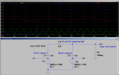
The attached screenshot shows an LTSpice simulation of this idea. V1,C1 is the first piezo; V2,C2 is the second. C3 is the 1nF external capacitor, wired in series with the output of V1, before adding that to the output of V2.
The green trace shows the raw output of V1 if nothing else were connected to it. The blue trace shows the same for V2 (I changed the frequency so you can easily tell V1 and V2 apart.)
And the red trace, of course, is the output, at the point where the direct output of V2 is joined to the through-the-1nF-cap signal from V1. You can see that the output of V1 has been halved in the mix - the high-frequency wiggles are only about 1 division in amplitude, instead of 2 divisions like the green trace.
Don't worry about magic capacitors with "good sound" - there is no such thing. I wouldn't use ceramic capacitors for this application, however, because they can be piezoelectric themselves, and might make thumping noises through your amplifier! So, use any type of film cap - Polyester, Mylar, whatever, it doesn't matter. A 50V rating is certainly adequate, more won't hurt if you can't find 50V caps (but don't buy caps rated for high voltages like 630 V, as they will be physically huge!)
-Gnobuddy
Attachments
I have a custom "stereo" cable that assuming I got the concept right, means I could have the resistor circuit hidden in the tailpiece of the bass (see attached)
Thanks! Yes it's a humbling instrument along with trumpet, trombone and likely several more instruments I'm not familiar with. But really, all instruments are difficult. some tell you up front and others let you know later as you're deeper in. It's also really hard to stand out as a guitarist - it's a deep instrument!
I've installed a few Piezo's in upright basses and it is certainly very tricky to
get an even natural sounding response.
There are a few options.
- The stereo jack OP with separate feed from each piezo is a good way to go
I don't think using a 1M passive potentiometer level control after each is the
best idea, depending on the OP level, the pot could introduce significant noise
purely due to the high value of resistance (Johnson noise) and the piezo
really wants to see a very high impedance for best sound. IME, an
active buffer fed directly from the piezo will give the best results.
- Another option is to make a dual active buffer + level control in a tiny box
with a single 9V battery. This can be mounted to the Bass with velcro etc.
FWIW, I've usually obtained best results using just 1 piezo and play with
the mounting location. How and where is your Piezo attached to the bass?
This makes a massive difference to the sound.
TCD
So how did this turn out? I happened to see this same thing a while back on the other forum:
I wanted to try a potentiometer or a resistor or two, but I was also concerned about Johnson noise.
I have a single element bass pickup (Realist Lifeline) that has a very hot output and causes many preamps to clip. (Actually, it's not just the "hotness," but the massive low end output that causes the clipping.) I used the single parallel capacitor idea in the end of an instrument cable, and it effectively pads the signal. I also thought it was rolling off a lot of high end at first, but then I tried cutting the bass even more (instead of boosting the highs), and that seemed to even things out a lot.Here’s an interesting data point...
On another forum, a bassist has a single sensor version of the same pickup that is too hot.
The solution from yamahiko is to add a capacitor from hot to ground...
This may give me some good values to work with.
I wanted to try a potentiometer or a resistor or two, but I was also concerned about Johnson noise.
- Home
- Live Sound
- Instruments and Amps
- inline attenuator of dual piezo pickups