"One listens to a system and not individual components" a wise man once said while not being able to distinguish individual components 🙂
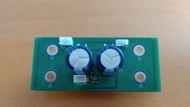
-input stage and 2 opamps removed, remaining 3 opamps replaced for OPA1642, output RCA removed including circuitry, almost all electrolytic caps replaced for Panasonic FC/FR, output coils replaced for 10A (5 mOhm) rated ones , coupling caps bridged with Wima 1 µF MKS. Bass boost switch removed and contacts bridged. That's it.
BTW I also used these coils in a Sabaj A10a and it made more difference in that one. Sabaj A10a has no bead or coil filtering except 4 x 1.5 nF caps used straight from each output to GND which one never sees elsewhere AFAIK. The Sabaj A10a is a newer revision without the ugly cutoff/sawn PCB and it now has bass whereas it previously was not as good in that area as the A8. This revision (no number) also has 4 identical 10 µF electrolytic caps for coupling the MA12070 to NJW1194 and it is already better than the previous 2020 version.
Just info for those that also like these amplifiers.
Last edited:

Hi all! I need a broadband (1-60kHz) power amplifier (1-10W) to sweep the output signal over a serial RLC circuit (R = 8-16 ohms, C = 0.2uF, L = 0.5mH), not for music. I have already ordered the ma 12070 board from Audiophonics.fr. My problem is that I haven't found which elements define the frequency band. Most graphics from Infineon have a very sharp cutoff at 20kHz. I'm assuming it's the digital cutoff on the input. On some other graphs, I have observed a normal (slow) cutoff, even around 100kHz, but again without any indication under what conditions this was obtained. May I ask the DIY guru to answer my question.
Not a guru but I think you have some items wrong. It is not digital, there is no digital cutoff as it is not digital and neither does it cut off at the input AFAIK, it has output filtering due to the nature of class D.
You probably have success by using only ferrite beads at the outputs as mentioned in the datasheet to avoid very high frequency products.
You probably have success by using only ferrite beads at the outputs as mentioned in the datasheet to avoid very high frequency products.
Jean-Paul, many thanks for your reply. I'm afraid my English is far from to be perfect and this creates some miss-understandings. I mean that a step-like cutoff at 20kHz is not due to some low-pass filtering which typically is proportional to w/wo^(-n), with n=1,2,3...., or 20dbu, 40dbu...per octave depending on the filter order. I also found the following results obtained for the same chip.,
see https://www.audiosciencereview.com/forum/index.php?threads/loxjie-a30-amplifier-review.17547/
see https://www.audiosciencereview.com/forum/index.php?threads/loxjie-a30-amplifier-review.17547/
A new but expensive MA12070P device came out. A lot of money for a low cost chip but maybe the extra streaming features (red knobs are liked by A8 owners too 😀) and software are worth the money and is the power amplifier just an extra?
https://volumio.com/en/product/volumio-integro/
https://volumio.com/en/product/volumio-integro/
Last edited:
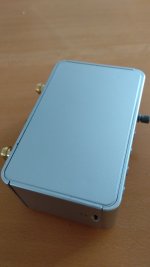
So whats your best bet on how to crack this nut open? I got it for 26USD shipped from Amazon.
Joints seem sturdy. There are 4 screws deep down under the feet which I undid without any apparent change. Brute force? Any ideas?
//
Joints seem sturdy. There are 4 screws deep down under the feet which I undid without any apparent change. Brute force? Any ideas?
//
Attachments

Last edited:
Yes - they come off. The screws sit deep at the very other end of the box. Feet seem to be of rubber and more or less break if you try to take them off.
//
//
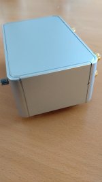
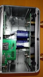
OK - so the bottom do come out once the screws are out and a bit of bending force is applied in one of the holes... looks like really well built, clean, structured with orderly marking of things.
I wonder:
I wonder:
- If and how one could mobilise the BT - I dont want that HF around.
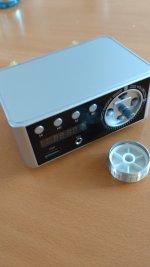
- The volume pot - is that "digital" control of the Infineon chip or do the analog signal pass it?
- In general make it into a power amp without any of the USB/card features...
- Exchange input caps
- Exchange output coils
Attachments

Last edited:
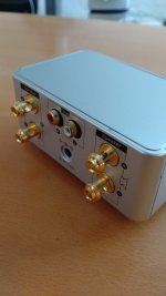
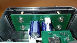
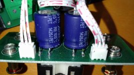
Can't be volume control of the MA12070 itself I think. Should be the other PCB. Nice amplifier board, I have seen worse. If you make detailed pictures of the sole amplifier board we can see if coils* will fit.
*On picture DSC_1001 we get a glimpse of SMD coils. Larger than on the picture in post 1327 (which also looks to be a completely different PCB).
Volume control seems to be logical when it really contains a MA12070P.
*On picture DSC_1001 we get a glimpse of SMD coils. Larger than on the picture in post 1327 (which also looks to be a completely different PCB).
Volume control seems to be logical when it really contains a MA12070P.
Last edited:
Except volume which probably is done via the 3 pin cables. Caps made in 2014, all normal since Covid 🙂
Interesting find. How does it sound?
Interesting find. How does it sound?
Yeah I guess. You may be OK with that but the loudspeakers and neighbors may not.
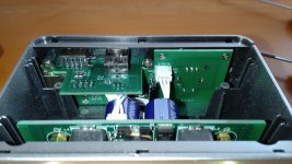
No wait I guess volume will be 0 as nothing connected so it will be open circuit. If you make a picture of both 3 pin connectors we can see that better. I think you'll need to connect those to eachother if you want to use the RCA connectors.
No wait I guess volume will be 0 as nothing connected so it will be open circuit. If you make a picture of both 3 pin connectors we can see that better. I think you'll need to connect those to eachother if you want to use the RCA connectors.
Last edited:
I do attenuation in my DAC so no problema. These white sockets - do one need to do something to let go of the connector or is it just to pull?
//
//
Careful pull the inner connector. Not the cable itself.
Hint: "open" power amplifier + volume control in DAC/source + small software error/glitch = catastrophe so sort of problema.
Also fiddly when pulling cables with the amplifier being switched on. Bzzz, BRRRRRR........ BTW you are busy with individual components if you were not aware of that 🙂
Hint: "open" power amplifier + volume control in DAC/source + small software error/glitch = catastrophe so sort of problema.
Also fiddly when pulling cables with the amplifier being switched on. Bzzz, BRRRRRR........ BTW you are busy with individual components if you were not aware of that 🙂
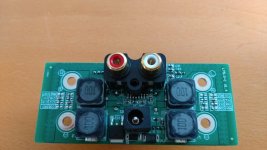

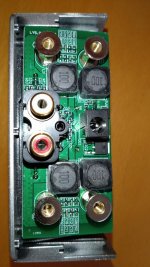
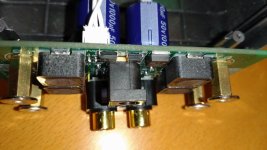
Not bad, they skimped on the capacitors as usual. Also they omitted the planned output network that you may wish to add being an audio rebel. I think removing the RCA connector block will make it possible to glue a heatsink to the chip and then you can use the cables to connect to better RCA connectors. If you'll use a new metal casing make sure to drill output connectors so that they'll fit exactly like the way it was in the plastic casing. Short signal path is always better, certainly with switching stuff. The back of the plastic casing is an excellent drilling template.
A small study to which output network and coils you wish may be necessary. The Infineon document will help you. Verdict from pictures: worth the money and probably fun to try out.
A small study to which output network and coils you wish may be necessary. The Infineon document will help you. Verdict from pictures: worth the money and probably fun to try out.
Last edited:
Ohh how i would like to get rid of the power and RCA sockets - but I know I will ruin the board most likely...
I will attempt, carefully, the RCA 🙂
//
I will attempt, carefully, the RCA 🙂
//
You may wish to use the "gentle total demolition ®" method. A 160 side cutter will do wonders. First cut off the heads of the snakes, so the white and red with shields sideways. Then the black part may be bent forward to do further connector dissection.
Power connector idem ditto. Gentle but remorseless demolition without any damage (= no mechanical force) to the PCB. One needs a fresh/sharp side cutter for connector sushi.
When the plastic is gone mostly removing the metal parts from the PCB is easy and done in seconds.
Power connector idem ditto. Gentle but remorseless demolition without any damage (= no mechanical force) to the PCB. One needs a fresh/sharp side cutter for connector sushi.
When the plastic is gone mostly removing the metal parts from the PCB is easy and done in seconds.
Last edited:
- Home
- Amplifiers
- Class D
- Infineon MA12070 Class D