DATA to SD0can I put an i2s signal directly on its input? I use Amanero.
Amanero Outputs: data, bclk,lrck,mlck, grn
ma127070 inputs: sck,ws,grn.sd0,sd1
BCLK to SCK (bit clock)
LRCK to WS (word clock)
GND to GND
MCLK would normally go to CLK input, but I don't see a connection for this, so I think the board is configured to just use bit clock.
DATA to SD0
BCLK to SCK (bit clock)
LRCK to WS (word clock)
GND to GND
MCLK would normally go to CLK input, but I don't see a connection for this, so I think the board is configured to just use bit clock.
I know nothing about the amanero board, but...
Hopefully the BCLK is a valid frequency (the MA12070P is a little finicky).
Will you have an I2C connection to the board to access/change the MA12070P registers? If not, you will need to flash the amenero board to match the MA12070P defaults of left justified and 32 bit.
I would assume the EN and MUTE pins are floating. To play, EN needs to be grounded and MUTE pulled high using the 3.3V output from your amenaro.
For BTL, verify the MSEL0 is 1 and MSEL1 is 0.
I hope I have all that right. Good Luck!
Mike
thanks Mike, Linuxfan.
I'm trying to connect and modify i2c. If it doesn’t go, I need to order an original amanero board and modify the firmware. I am now using a Chinese clon amanero board. this cannot be updated, just spoiled.
I'm trying to connect and modify i2c. If it doesn’t go, I need to order an original amanero board and modify the firmware. I am now using a Chinese clon amanero board. this cannot be updated, just spoiled.
DATA to SD0
BCLK to SCK (bit clock)
LRCK to WS (word clock)
GND to GND
MCLK would normally go to CLK input, but I don't see a connection for this, so I think the board is configured to just use bit clock.
Yes ,the board is configured to just use bit clock.
Hi Michael et al,
Can you clear something up regarding the MA12040 board I have, please?
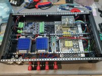
As detailed in my thread (Workshop Co-ax Mini Bangers - B&C 5CXN44) I have put together a 4 channel amp from 2 bvoards. One MA12070 with 24v/150w PSU and one MA12040 with 18v/100w PSU.
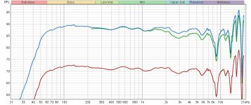
When I did distortion tests on my speaker I noticed that the tweeter powered by the MA12040 board (crossed at 18k) lagged behind by 2db output.
It's very confusing, should this MA12040 board actually be powered by 24v? Is this the caused for the difference in behaviour?
- Red is level I designed the crossover at
- Green is the level I tested disortion at
- Blue is the same as the red but lined up with the distortion test to show the discrepency
Can you clear something up regarding the MA12040 board I have, please?
As detailed in my thread (Workshop Co-ax Mini Bangers - B&C 5CXN44) I have put together a 4 channel amp from 2 bvoards. One MA12070 with 24v/150w PSU and one MA12040 with 18v/100w PSU.
When I did distortion tests on my speaker I noticed that the tweeter powered by the MA12040 board (crossed at 18k) lagged behind by 2db output.
It's very confusing, should this MA12040 board actually be powered by 24v? Is this the caused for the difference in behaviour?
- Red is level I designed the crossover at
- Green is the level I tested disortion at
- Blue is the same as the red but lined up with the distortion test to show the discrepency
Attachments
Last edited:
Hi ,
For MA12040 the max voltage supplly is 18V, so you can't supply with 24V absolutly. If you want test this two ICs in the same condition, you can supply with 18V both.
From the two datasheets, it shows some wispy different originaly. And I think MA12040 is the rest form product line test. If it pass all of the test so marked with MA12070, if it failed with some test item it marked with MA12040(Just my guess). So it will have some different parameter like internal power MOS Rdson and so on.
Thanks!
Both chips are 20 dB gain in their default configuration, but you can easily measure the gain of each at 1 KHz to verify. Other than than that I would investigate you woofer & tweeter frequency response (FR) measurements and your SigmaStudio program.
(In case you didn't know): SigmaStudio normalizes FR measurements when you load them. For example, let's say your tweeter measurement is 5 dB higher in SPL than your woofer measurement. Re-check them after you load them into SigmaStudio - they'll both have the same max SPL (usually + 5 dB). So you need to adjust the tweeter level in SigmaStudio for that.
(In case you didn't know): SigmaStudio normalizes FR measurements when you load them. For example, let's say your tweeter measurement is 5 dB higher in SPL than your woofer measurement. Re-check them after you load them into SigmaStudio - they'll both have the same max SPL (usually + 5 dB). So you need to adjust the tweeter level in SigmaStudio for that.
Thanks Michael and Ed.
My thoughts were that there was some sort of throttling from an underpowered PSU but my understanding of this isn't top notch - obviously 🙂
Michael, that is very confusing. When I first got the PL-AD-160 board with the MA12040 IC I wrote it off as an unusable unit but after testing with 18v and it worked fine I thought different. However, I don't quite understand how a seemingly identical board would work with a younger sibling so well. The silk screen reads max voltage to be 26v. I wondered if there were some sort of voltage regulation for the MA12040 I can't see?
Ed, yes, this was my first thought that it was a DSP issue however, I am using a MiniDSP and doubled checked the compressor settings. I haven't had any issues like this in the past with this unit.
The chin scratching continues.
volume control
I have a Merus12070p chipboard. I want to use an amanero usb to i2s converter. how to adjust the volume? if i play pcm then the volume control of the player software works. but if there is native dsd playback, it cannot be controlled by software. is it possible to control it via the i2c bus inside the merion chip? what do you need to add?
I have a Merus12070p chipboard. I want to use an amanero usb to i2s converter. how to adjust the volume? if i play pcm then the volume control of the player software works. but if there is native dsd playback, it cannot be controlled by software. is it possible to control it via the i2c bus inside the merion chip? what do you need to add?
I have a Merus12070p chipboard. I want to use an amanero usb to i2s converter. how to adjust the volume? if i play pcm then the volume control of the player software works. but if there is native dsd playback, it cannot be controlled by software. is it possible to control it via the i2c bus inside the merion chip? what do you need to add?
The combination of registers 0x40 and 0x41 control the Master Volume of the MA12070P. By default 0x40 is set to 0x18 and 0x41 to 0x00 (0 dB). Page 20 of the datasheet details the available settings to change the gain levels.
I don't know anything about the amanero, but it looks like you can code i2c commands to modify registers based on certain events(?).
Mike
i2c volume control
yes i was looking at the datasheet. but the question really is, can i adjust the volume via i2c? e.g. with ardunio or what?
I am interested in a practical solution. how? usb-usb digital volume control module not found. 🙁
yes i was looking at the datasheet. but the question really is, can i adjust the volume via i2c? e.g. with ardunio or what?
I am interested in a practical solution. how? usb-usb digital volume control module not found. 🙁
diy amp
Hi everyone,
I thought I join your discussion about the ma12070p.
This summer I started with DIY HiFi projects and build my first active F.A.S.T desktop speaker using Wondom jab3 boards with DSP crossover and room compensation.
Now I try my luck with circuit board design 😀
@matt_garman thank you for providing the Kicad schematic, I used your example for implementation in EasyIDE. The reason is, that it looks like a good starting point for beginners. I also have tried Kicad and think it's doable for me, but right now I want to focus on design.
My goal right now is, to find the correct parts for the LC output filter. Although I have a reasonable soldering and hot air station, I don't have a reflow oven or plate heater. Therefore is want most parts of PCB assembled by the manufacturer, in this case, JLCPCB.
My plan is to use 0805 SMD for all generic components (according to the design recommendations) because they are available as basic parts and still can be soldered by hand.
All critical components should be through-hole, to allow changes. Mostly the output filter components.
I don't know if the usage of the reference Design provided by Infineon is restricted in any form, but I'm planning to release the PCB as a open-source project on Github, including schematics, layout, BOM, documentation, etc.
The FreeDSP project looks very cool, so this might be a suitable Board for it.
If someone is interested to join forces or sharing his experience with LC filter designs for class D amps, every help is very much appreciated!
Best
Fabian
The combination of registers 0x40 and 0x41 control the Master Volume of the MA12070P. By default 0x40 is set to 0x18 and 0x41 to 0x00 (0 dB). Page 20 of the datasheet details the available settings to change the gain levels.
I don't know anything about the amanero, but it looks like you can code i2c commands to modify registers based on certain events(?).
Mike
Has anyone changed the gain with I2C yet?
Hi Folks, I hope you are doing great, I have a question for you, I was giving a look to the Raspberry variant PL-DD-140W, this board has two fixed output connectors for stereo configuration (2X80W), but I was wondering if this one may be 2.1 configurable, I did not see any pin selector like in the PL-AD-160W.

I will appreciate any help you can provide.
I will appreciate any help you can provide.
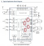
I mean the output transistors in the output stage on this block diagram of the "chip". They could be GAN Fets?
Or you know Infineon make their own fet output devices.
Or you know Infineon make their own fet output devices.
Attachments
Last edited:
Hi guys . I ordered 2 evaluation cards in addition to my Sabaj A20a, to power my center speaker and rear speaker ... https://www.infineon.com/cms/en/product/evaluation-boards/ref_audio_a_ma12070/
Pillor electronic cards leave me skeptical ...
In view of the length of my speaker cables, it is necessary to filter the EMI.
I am thinking of recovering the old inductors from an old 3116 tpa.
Good idea or not ? 🙄
Pillor electronic cards leave me skeptical ...
In view of the length of my speaker cables, it is necessary to filter the EMI.
I am thinking of recovering the old inductors from an old 3116 tpa.
Good idea or not ? 🙄
MA12070(P) and MA12040(P) family does not use GaN. Actually it also doesn’t use SiC. It uses a so-called BCD process which includes Bipolar, CMOS and DMOS technology in one process.I mean the output transistors in the output stage on this block diagram of the "chip". They could be GAN Fets?
Or you know Infineon make their own fet output devices.
Even it is suggested inductors instead of ferrite for more than 80cm cable. I suggest you to try first without make any swap. If you do not hear any of those noise no need such an action. In my case i am not using inductors instead 4 ferrite beads in contras 2 ferrite in standard. To do so i run chip in mono mode.Hi guys . I ordered 2 evaluation cards in addition to my Sabaj A20a, to power my center speaker and rear speaker ... https://www.infineon.com/cms/en/product/evaluation-boards/ref_audio_a_ma12070/
Pillor electronic cards leave me skeptical ...
In view of the length of my speaker cables, it is necessary to filter the EMI.
I am thinking of recovering the old inductors from an old 3116 tpa.
Good idea or not ? 🙄
- Home
- Amplifiers
- Class D
- Infineon MA12070 Class D