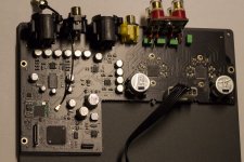
Decoupling seems to have gotten enough attention. I notice the fine Chinese stainless steel inbus bolts though 🙂 If they are of the known quality then they will strip the first time one wants to detach them.
Last edited:
I have taken apart more cheap amps than I care to count. I have not encounter too many problems with screws. I have also notice the quality of the PCB for the cheap amp has actually improved a bit over the years (by that I mean the soldering and desoldering on the board).
Hi, yes I noticed the same. Desoldering and resoldering used to be stripped PCB tracks but today less so.
Yes it's the standard WROOM32D.
I developed all with the ESP-IDF toolchain. For connecting to the MA12070P i made a custom driver.
For the analog-input there is a dedicated ADC chip (PCM1808) on the board which is running the audio through the DSP in the ESP32.
Forgot to ask 😱. How do you source MCLK to the MA12070P?
Mike
Hey guys!
See one of my latest projects with the MA12070P on my YouTube channel:
[#26.1] 4-Channel DSP Bluetooth Amplifier - Intro - YouTube
[#26.2] 4-Channel DSP Bluetooth Amplifier - Live Demo - YouTube
Do you plan on selling the board in the near future? I'm really interested!
I got my AliExpress MA12070p amp to work with the I2S outputs of a ADAU1701 DSP. The ma12070p amp (Shenzhen Pillor, V1.4) is unmodified and uses all the factory defaults (Left justified, 20 dB gain, etc.). I configured the ADAU1701 I2S outputs as follows:
-Master mode
- LRCLK low on left channel
- BCLK falling edge
- LRCLK frame sync
- Frame Sync Freq = internal clock/1024
- MSB Position = delay by 0 (NOTE!)
- Word Length = 24 bits
- BCLK frequency = internal clock/16
My ADAU1701 has a 12.288 MHz crystal (internal clock = 49.152 MHz). This makes BCLK = 3.072 MHz and LRCLK = 48 KHz (could support 32 bit words).
My amp came with a cable so I tied the amp's SCK and SD1 lines to the DSP's BCLK line. Other connections were DSP's LRCLK to amp's WS, DSP GND to amp GND and DSP I2S data to amp SD0.
In case you are interested, I found a very interesting document in the internet, showing the internal of the SOUNDBOKS 3 (which is MA12070P based).
Seems they're using standard BTL mode and one of the four channels unused.
https://fccid.io/2AJAASB3/Internal-Photos/Internal-Photos-4455704.pdf
Seems they're using standard BTL mode and one of the four channels unused.
https://fccid.io/2AJAASB3/Internal-Photos/Internal-Photos-4455704.pdf
CLK Needed at Startup?
A question for those that have successfully implemented the MA12070p using bit clock only, shorting pins 21 and 32 together...
Does your source provide bit clock at startup? I just discovered that my ESP32 doesn't, bit clock starts when I press play. The datasheet says that CLK pin 32 must have a valid clock at startup. Perhaps this is the reason I cannot get my amp to play?
Thanks, Mike
I have following setup.
Passive pull-up on /ENABLE and passive pull-down on /MUTE. So that the default state is disabled and mute-on.
First thing is to init the I2S interface so that the clocks are getting present.
Afterwards init the /ENABLE gpio on uc and tie to GND (amp gets active).
/MUTE pin is only enabled in case the software can ensure, that there is valid audio data going out on I2S interface.
If there is no audio-data available to push out, directly set /MUTE to GND again.
So your software-concept is a little bit the wrong way.
If you are using 32-bit LSB audio-standard you don't have to configure anything over i2c to get it running. Otherwise you can do the I2C init after I2S-clocks are running and /ENABLE pin is to GND (but with mute active).
Then it is starting up without any plops or similar.
I have following setup.
Passive pull-up on /ENABLE and passive pull-down on /MUTE. So that the default state is disabled and mute-on.
First thing is to init the I2S interface so that the clocks are getting present.
Afterwards init the /ENABLE gpio on uc and tie to GND (amp gets active).
/MUTE pin is only enabled in case the software can ensure, that there is valid audio data going out on I2S interface.
If there is no audio-data available to push out, directly set /MUTE to GND again.
So your software-concept is a little bit the wrong way.
If you are using 32-bit LSB audio-standard you don't have to configure anything over i2c to get it running. Otherwise you can do the I2C init after I2S-clocks are running and /ENABLE pin is to GND (but with mute active).
Then it is starting up without any plops or similar.
I should have added the fact that the ref board I'm using has jumpers, /MUTE==>VDD and /ENABLE==>GND, so I can't control these pins. I'm assuming those steps in the suggested startup are not really needed. It's the CLK pin I'm curious about...does it need to have a valid clock frequency at startup? The Squeezelite-ESP32 firmware I'm using seems to not output the bit clock until I press play, and I wonder if that's my problem.
Thanks, Mike
Never Mind! I don't know when I got the registers correct, but the problem ended up being a bad speaker connection. I only had the left speaker connected and that was bad. Had I connected the right speaker during testing I would have had this going a long time ago 🙁
I got my AliExpress MA12070p amp to work with the I2S outputs of a ADAU1701 DSP.
Which make DSP are you using?
How do you plan to control volume?
Last edited:
Is it possible to connect the i2s from a Wiimu directly to the MA12070?
Wiimu A31 / Linkplay / Up2Stream i2s information Form this topic:
Wiimu A31 module in combination with ADAU1401/1701 DSP
"the A31 module is operating in slave mode with bclk and lrclk being generated by the onboard audio processor of the Up2Stream module. The I2S output of the A31 module is 16-bit with a sample rate of 44.1kHz. All of the audio is thus resampled to this sample rate... The A31 module can thus be interfaced directly to a ADAU1701/1401 DSP as long as the correct bclk and lrclk signals can be generated"
The author explains the DSP needs to act as the master and finds a work around by replacing the crystal on the ADAU1401. However I would like to connect a31 directly to the amplifier i2s?
It MIGHT work with the I2S version (i.e. the MA12070p) of the amp. The Wiimu has the I2S signals needed, just be sure to connect MCLK to the SD1 input. The MA12070p spec sheet (Table 8-11) shows the different MCLK frequencies that will work at Fs = 44.1 KHz.
However, there's also the I2S format to consider. The M12070p spec sheet lists the default values in Table 8-8. I don't know the Wiimu uses for its I2S format.
However, there's also the I2S format to consider. The M12070p spec sheet lists the default values in Table 8-8. I don't know the Wiimu uses for its I2S format.
I have been using the MA12070 analog board version from Aliexpress for a few months now and wanted to know if anyone has experimented with different value AC-coupling caps with the amp operating in BTL mode using unbalance configuration. The bass response seems a bit lacking and the stock ceramic caps used look to be just 1uF. When looking at the datasheet from Infineon they show an application block diagram on page 3 with 10 uF caps used in balanced mode, but when I go to page 24 they suggest 1uF caps in low gain mode and 2uF caps in high gain mode for PBTL. The caps noted are X5R ceramic type that have specified temperature tolerance with an allowable temperature range of +/-15%. The datasheet lacks information in this area and I don't want to take any risks damaging this chip. Judging by this amp it seems to be configured in low gain mode.
Has anyone had any long term success using different values of caps and types of caps for coupling replacing the stock ones on this board?
Has anyone had any long term success using different values of caps and types of caps for coupling replacing the stock ones on this board?
Hi all, which power supplies are you using with the boards?
I'm about to buy few MA12070 boards from audiophonics.fr but the 24V smps they sell (Mean well) are either too small ~100W or big ~350W.
Do all amp boards need to have their own psu? I'm putting multiple amps into a single enclosure and I'd like to power multiple from one smps or use multiple small smps. I don't have enclosure yet so the size is just a preference than strict limitation.
Any tips what to get for power supply? Thanks
There is not such a thing as too much power but ...extremely overrated when using SMPS is not advisable. Check maximum continuous power and use a PSU that can deliver 1.5x that power. Separated PSU's are better. Dual mono....
When used in PBTL mode so 160W/4Ohm it should be OK when using a 26V 200W per channel for normal/average use.
When used in PBTL mode so 160W/4Ohm it should be OK when using a 26V 200W per channel for normal/average use.
Last edited:
Found this EPP-300-24 | Mean Well Embedded Switch Mode Power Supply SMPS, 24V dc, 8.33 A, 12.5 A, 200W Open Frame | RS Components
Nice form factor and modern LLC topology. Is there anything why this psu wouldn't work? one per amp.
Nice form factor and modern LLC topology. Is there anything why this psu wouldn't work? one per amp.
Last edited:
- Home
- Amplifiers
- Class D
- Infineon MA12070 Class D