My stm32 work with 3.3v logic as well, but it's enough for communication. I2c bus pulled up with 4.7k resistors from stm32 side
Someone PM'ed me asking for the schematic, BOM, etc for the board I made, see post #403.
Attached are the following:
Attached are the following:
- Schematic in PDF format
- Zip file containing BOM in multiple formats (PDF, Excel, OpenOffice, CSV)
- KiCad files
- Gerber files I sent to JLCPCB for fabrication
Attachments
So, finally got fully working aliexpress board (blue one, i2s 12070p version).
Here is BOM and instructions:
5x 1kOhm resistors (3 for i2s bus and 2 for i2c bus)
3.3 <-> 5v Level convertor (~$1) (you can make one if you'd like, it's really optional because it will give you full Merus official driver functionality with /EN and /MUTE but by default board of v1.4 goes to the correct mode of EN->0 and MUTE -> so, it will be just working)
So, after you get everything you have to pull down SCK,WS,SD0 on aliexpress merus board and connect SD0 to SCK. Also you need to pull down SCL and SDA as well.
After that you need to do the following connections:
MERUS RPI Zero
SDA -> PIN3
SCL -> PIN5
SCK -> PIN12
WS -> PIN35
SD0 -> PIN40
GND -> PIN14
GND -> PIN14
EN -> PIN8
MUTE -> PIN10
After that you can take latest volumio player for Rpi Zero and install it. Right after you did that you need to select MERUS RPiZ HAT, save and restart it. Upon boot your player is ready 🙂 Volume can't be controlled from volumio because of the bug in volumio but you can do that via ssh using alsamixer.
I can forget about some details so don't hesitate to ping me.
Better to purchase Rpis from official stores. On AliExpress they probably would be expensive. I would recommend just go with "Raspberry Pi Zero Wireless" it works just fine for that.
Hello colleagues.
The most important thing I want to know is your impressions of the sound of the MA12070R.
This chip has four DACs, probably very simple and primitive.
If you compare the sound with the MA12070 and an external DAC, is the difference significant?
The most important thing I want to know is your impressions of the sound of the MA12070R.
This chip has four DACs, probably very simple and primitive.
If you compare the sound with the MA12070 and an external DAC, is the difference significant?
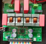
Here is version 2 of my ma12070p PCB. Same circuit, just went for complete overkill components, mostly in the output filter. I made room for the big Coilcraft VER29xx series inductors. I sprung for 2oz copper pour on the PCB too.
I'm starting to doubt my ability to solder these tiny SMD components (i.e. the ma12070p chip) using the stovetop skillet method. The picture is actually my third try at soldering this. The first two had visible solder bridges on the ma12070p chip pins. I tried to clean them up with braided solder wick, but couldn't make them work. I feel like I got lucky on the version 1 board, it just worked without any cleanup. I'm thinking I might just have the fab house do the SMD soldering for me in the future.
Anyway. Another interesting observation: earlier in the thread, I was using Infineon's reference board (the tiny PCB, barely bigger than a postage stamp), and remarked that with some speakers, the board itself made a hissing sound. That happened initially with my v2 board too. But that was because I did the initial test without the output filter (I just soldered a wire where the big inductors go). But once I populated the LRC output filter, the hissing stopped.
Attachments
Nice work Matt Garman! Try skillet from bottom and hot air pencil from top. Get ENIG finish and don’t use too much paste. Apply paste with 22gauge “Henna” blue plastic taper nozzle for precise paste lay down. Use low temp (150C) no lead paste.
Skillet heat only to ~125C. Let hot air pencil at 350C melt paste locally.
Use expensive ($6/roll) fine mesh copper braid with thin water like liquid flux on braid to clean pins after. They should look clean and uniform. Use fat chisel tip iron on braid.
Skillet heat only to ~125C. Let hot air pencil at 350C melt paste locally.
Use expensive ($6/roll) fine mesh copper braid with thin water like liquid flux on braid to clean pins after. They should look clean and uniform. Use fat chisel tip iron on braid.
Last edited:
Nice work Matt Garman! Try skillet from bottom and hot air pencil from top. Get ENIG finish and don’t use too much paste. Apply paste with 22gauge “Henna” blue plastic taper nozzle for precise paste lay down. Use low temp (150C) no lead paste.
(snip)
Thanks, X! I saw your similar suggestions in the tpa3250 thread as well.
I think I will invest in a hot air pencil and try your method. The taper nozzle will be a big win as well, thus far I've just used a toothpick to spread solder paste!
Question: have you (or anyone else) used this method for soldering "thermal pad down" chips like the ma12070(p), tpa3250, tpa3118, etc? I.e., ICs that are designed to use the PCB as a heatsink? Is it safe to assume that if the hot plate bottom + hot air flow on top is enough to melt the chip pin solder, that it also melted the thermal pad solder?
Edit: I know your tpa3255 board uses the big Coilcraft SER-style inductors, basically the flat, SMD version of what I used above. Were you able to easily solder those as well using the your hotplate bottom + hot air top method? I've soldered those before with a regular soldering iron, and it's a challenge, those inductors absorb so much heat. The VER-style that I used are nice for space-savings and being through-hole. But the SER-style are cheaper, and also other manufacturers make inductors with the SER-style footprint, another win for price and availability.
Last edited:
Yes, the hotplate on the bottom and hot air pencil on top lets me solder thermal pads to vias very effectively. I have done LME49724 this way, as well as OPA1622 in VSON10's, many tiny MOSFETs, the CoilCraft SER's, some Murata SMT DC/DC converters, and even a large DSP chip. The most difficult things to solder with just hot air or just hot plate are large SMT electrolytic caps. The hot air alone melts the plastic base before heating the pads on the bottom. So both bottom hot plate and top hot air is useful. They make hot air rework stations where hot temp stabilized air is blown from bottom so that it allows double sided boards to be reworked. I have not found a need for that yet.
Does anyone know what it means when both the ERROR and CLIP lines go low on the ma12070p? I attempted to finalize my v2 build: swap out power supply and actually bolt everything to the chassis. No changes to the actual ma12070p board (other than the physical mounting). Now, at power on, both ERROR and CLIP lights turn on. I cannot talk to the board via I2C.
I put my v1 board in its place, it works fine. So it appears I must have some how damaged the v2 board while doing the mechanical work. But since I can't even talk to it via I2C, I have no idea what is wrong. The datasheet doesn't seem to give any hint as to what the problem might be.
I checked 5v and 24v supplies, they look OK (about 5.16v and 23.3v, respectively).
Any thoughts?
What is the power consumption of the MA? Are the clock and reset signals ok?
Do you have diodes to protect IC from freewheeling currents? It's quite easy to set MA on fire without them with such big inductors...
Do you have diodes to protect IC from freewheeling currents? It's quite easy to set MA on fire without them with such big inductors...
Hi, going to share my experience. I use 3.3uH inductor as Infineon recommended in this pdf (page 5) - EMC recommendations
First time I use 1uF for the filter PET Cap and 2.2uF for damping ceramic Cap. My speakers are 4 and I hear no inductor noise (almost) with speakers connected.
But after that I re-read this PDF file and found info in brackets: 1uF for the damping capacitor and 0.47uF for the PET filter capacitor.
Ok, done. Now the caps palced as descirbed in the doc. But now the noise come from inductors and it very noticeable. So I decide to get back my 2.2uF and 1uF caps. Anyway, need to calculate cut-off frequency for that filter. Hope I will not cut less than 22kHz 🙂
Here are two videos that show the LC filter problem
With noise
0.47uF and 1uF with L noise - YouTube
Without noise
1uF and 2.2uF without L noise - YouTube
Hi, going to share my experience. I use 3.3uH inductor as Infineon recommended in this pdf (page 5) - EMC recommendations
First time I use 1uF for the filter PET Cap and 2.2uF for damping ceramic Cap. My speakers are 4 and I hear no inductor noise (almost) with speakers connected.
But after that I re-read this PDF file and found info in brackets: 1uF for the damping capacitor and 0.47uF for the PET filter capacitor.
Ok, done. Now the caps palced as descirbed in the doc. But now the noise come from inductors and it very noticeable. So I decide to get back my 2.2uF and 1uF caps. Anyway, need to calculate cut-off frequency for that filter. Hope I will not cut less than 22kHz 🙂
Here are two videos that show the LC filter problem
With noise
0.47uF and 1uF with L noise - YouTube
Without noise
1uF and 2.2uF without L noise - YouTube
Can you please try with following:
L=1.5uH
C (L to GND) = 220pF
R-C Snuber = 75 Ohm + 6.8nF
Don't expect a fully restored audio-waveform at the output, but the filter is enough to meet cispr-55032 with 3 meters cable (tested myself).
The noise should be definitely not present.
Did you test it exact with MA12070 amp? What kind of waveform losses I need to expect, what cut-off frequency? I start to explore softwares that can simulate class D low-pass filters. So I just use only Infineon recommendations as a starting point.Don't expect a fully restored audio-waveform at the output, but the filter is enough to meet cispr-55032 with 3 meters cable.
Thanks for advice, try to find those components for the test.
Did you test it exact with MA12070 amp? What kind of waveform losses I need to expect, what cut-off frequency? I start to explore softwares that can simulate class D low-pass filters. So I just use only Infineon recommendations as a starting point.
Thanks for advice, try to find those components for the test.
You will still see the multi-level PWM at the output of the filter, but the switching-edges have a slightly rounded shape.
The filter was designed to have significant drop starting at around 30 MHz because this is the point where antenna-measurement in EMI compliance normally start.
EDIT: I used the MA12070P
Last edited:
Keep care about the saturation current which should be minimum as high as the current-limit of the power stage. It is specified in the datasheet but I’m not sure 100% anymore. Should be around 6 amps
- Home
- Amplifiers
- Class D
- Infineon MA12070 Class D