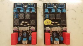
I have the 3116 YJ Danz board V2 - cheapie from China. I used the same one before for a streaming device with Raspberry Pi without issue.
This one has a slighter higher voltage SMPS - the Meanwell PPS 125 -24.
I'm sure the board should handle 24V. I connected it last night to a 4R Sub woofer and played with it for half hour. I noticed it was very hot afterwards.
So tonight I thought I would just idle it with nothing connected (Input or Output) - Just the 24V power supply.
The inductor on the right channel closest to the chip got too hot to touch within minutes. The heatsink of the chip followed even though I could hold my finger on it for an amount of time - it was incredibly hot.
I also did the mods as per the wiki here, including the bootstraps - could this have caused the problem?
Stu
They maybe have wrong inductor core.
Try a t106-2 core with as many turns that are currently on the output inductor.
Try a t106-2 core with as many turns that are currently on the output inductor.
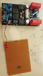
OK, have attached a pic showing the inductor that is hot. I was planning on possibly putting this board into PBTL anyway so I figure now is worth a try seeing as something is up with the board.
Could someone explain to me which channels the inductors serve? Or better still a simple explanation of which side I should be putting this board into PBTL if I don't want this inductor that gets hot to be used.
I just don't quite understand how PBTL mode gets routed through the chip and out through the various filters
stu
Attachments
Last edited:
Never leave the output unconnected, or you'll be asking for trouble 😉
+1
Can anyone confirm the statement from theaspin. I would have thought only two inductors would be used as HF filters in PBTL mode?
Another member says "PBTL is parallel bridge tied load and uses both left and right circuits as one (only 2 inductors) in mono"
stu
Another member says "PBTL is parallel bridge tied load and uses both left and right circuits as one (only 2 inductors) in mono"
stu
You can use only two, but that will require extra soldering. The basic PBTL mod is done by connecting both left channel inputs directly to ground and by shortening each stereo output pairs to create single output pair.
Feeling quite pleased with myself, sure I won’t make any impressions round this forum but thought I’d share my findings and solution.
I have two boards so I decided to do the old logical comparison tests to find why my inductor was too hot to touch. Firstly I did continuity tests all over each board and everything seemed fine. Then I set the DVM to capacitance mode and discovered I could read 680nF on all caps in all output filters except the one with the suspect inductor. This cap couldn’t even get a read on my meter.
So I removed it, and found the marking 22nk400 on it. Wow, my board had totally the wrong component here. 22nF, the rest are 680nF which is what TI recommend.
I had some 220nF caps lying around so I paralleled 3 of these up to make 660nF and ….
No more over heating inductor!
I have read about people receiving the wrong gain resistors, hope this may help anyone troubleshooting these cheap Chinese boards.
Thanks again to everyone here, and thanks theaspin for clearing PBTL query up. Next step is to do the simple version of the PBTL mod and research a better filter for my sub bass amp.
Will be using my 4oHm 10 inch sub driver for a while, but soon I will be seeking out a 2oHm 10 inch driver….
Stu
Attachments
Oh, and do these 680nF capacitors in the output filter affect quality if I am to keep the stock inductors?
found these from my local supplier:
MKT1817-468-065 | Vishay 680nF 10% 40 V ac, 63 V dc Through Hole Polyester Film Capacitor MKT 1817, MKT1817 | Vishay
or could I go even cheaper here? In keeping with my chinese cheapies...
Stu
found these from my local supplier:
MKT1817-468-065 | Vishay 680nF 10% 40 V ac, 63 V dc Through Hole Polyester Film Capacitor MKT 1817, MKT1817 | Vishay
or could I go even cheaper here? In keeping with my chinese cheapies...
Stu
affter replace 680nf . hight noise can u hear?Oh, and do these 680nF capacitors in the output filter affect quality if I am to keep the stock inductors?
found these from my local supplier:
MKT1817-468-065 | Vishay 680nF 10% 40 V ac, 63 V dc Through Hole Polyester Film Capacitor MKT 1817, MKT1817 | Vishay
or could I go even cheaper here? In keeping with my chinese cheapies...
Stu
On MY YJ Blu / black YJ board Cheapie, to which I added an Input pot/volume control, ALL the inductors got warm.
Until I realised I had erm.. bungled 😱 the pot wirings.. which, when redone 'properly' the heating disapeared and the Volume went up.. a lot 🙂
Still sounds like Crap (harsh and Shrill) though.
Making my old YJ ta 2020 cheap *** Board sound like heaven by comparison.
Until I realised I had erm.. bungled 😱 the pot wirings.. which, when redone 'properly' the heating disapeared and the Volume went up.. a lot 🙂
Still sounds like Crap (harsh and Shrill) though.
Making my old YJ ta 2020 cheap *** Board sound like heaven by comparison.
- Status
- Not open for further replies.
- Home
- Amplifiers
- Class D
- Inductors too hot to touch on YJ 3116