I feel this area of solid state is not very popular so I've built something to try it out.
The concept is for a single ended, single stage, no-feedback, inductively coupled class A power amplifier. Inductive loading gives a welcome rise in efficiency above the theoretical 25% limit to a new theoretical 50% limit. In reality 35 - 40% is a reasonable limit.
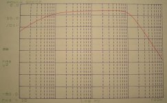
The frequency response of such an amplifier is limited in the high end by the transistor and surrounding circuitry, while the low end is limited by the inductance of the inductor and surrounding circuitry to a lesser extent unless coupling capacitors are in use.
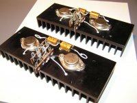
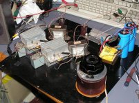
My prototype is a monoblock using Germanium transistors, just to put an interesting spin on things. I used the 2N2080 doorknob style transistor from Motorola. At a minimum 5kHz fT, this is a wonderfully slow transistor.
I've chosen a 64mH choke to give a rolloff of 20Hz on the bottom end for 8ohm drivers. The output is capacitively coupled to the speaker.
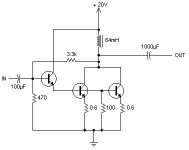
Shown is a schematic of the actual operating prototype. The 64mH inductor and 1000µF cap should give a LF rolloff near 20Hz at 12dB/oct (LC filter).
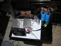
Impressions so far are that this sounds pretty good, as bad as it really looks.
The concept is for a single ended, single stage, no-feedback, inductively coupled class A power amplifier. Inductive loading gives a welcome rise in efficiency above the theoretical 25% limit to a new theoretical 50% limit. In reality 35 - 40% is a reasonable limit.
The frequency response of such an amplifier is limited in the high end by the transistor and surrounding circuitry, while the low end is limited by the inductance of the inductor and surrounding circuitry to a lesser extent unless coupling capacitors are in use.
My prototype is a monoblock using Germanium transistors, just to put an interesting spin on things. I used the 2N2080 doorknob style transistor from Motorola. At a minimum 5kHz fT, this is a wonderfully slow transistor.
I've chosen a 64mH choke to give a rolloff of 20Hz on the bottom end for 8ohm drivers. The output is capacitively coupled to the speaker.
Shown is a schematic of the actual operating prototype. The 64mH inductor and 1000µF cap should give a LF rolloff near 20Hz at 12dB/oct (LC filter).
Impressions so far are that this sounds pretty good, as bad as it really looks.
Attachments

Gotta applaud your exploration into uncharted SE territory.
Or at least an area that hasn't been visited in a great while.
http://electronicdesign.com/Articles/Index.cfm?AD=1&ArticleID=4555
Sadly, IGBT's don't seem to get much attention either...
Or at least an area that hasn't been visited in a great while.
http://electronicdesign.com/Articles/Index.cfm?AD=1&ArticleID=4555
Sadly, IGBT's don't seem to get much attention either...
That's an excellent article on trying to overheat the Ge transistor.
I've had similar experience with certain OnSemi power silicon stuff. I had an MJL21193 de-solder itself from the circuit during overload condition. It worked perfectly upon re-connection. The die temperature must have been unreal.
I've had similar experience with certain OnSemi power silicon stuff. I had an MJL21193 de-solder itself from the circuit during overload condition. It worked perfectly upon re-connection. The die temperature must have been unreal.
kenpeter said:
Sadly, IGBT's don't seem to get much attention either...
With enough feedback any device can sounds good. Now just grab some beer and watch all the mid life crisis fanbois and 'experts' get all worked up.
The absence of a P-type device pretty much eliminates the prospect of use in audio. Circuits that look symmetrical on paper on very much the fad. There probably are P-type devices, I just haven't seen one. When you're driving 5000HP pumps with VFD's efficiency is of the essence, and we don't care so much about symmetric looking circuits. It's fewer parts to stock too.
If I get an IGBT I will try it out in some single ended and perhaps also push pull amplifier circuits. (In the case of push-pull, it would be 'pulled' on by a different kind of device unless I find complementary devices).
Another thing: what about IGBTs in quasi complementary mode? Then a pair of the typical N stuff will be just right.
For single ended circuits like the one this thread proposes, the single IGBT is worth a try when I get my hands on one.
Another thing: what about IGBTs in quasi complementary mode? Then a pair of the typical N stuff will be just right.
For single ended circuits like the one this thread proposes, the single IGBT is worth a try when I get my hands on one.
If anybody wants to try the germanium design at the start of the thread, I have a pair of good TO-3 BEL AD149s and a few BEL AC125s, 128s and 127s - there's enough for two channels. I'd prefer a local buyer - PM me if there's any interest.
Here I have made another version of the circuit mentioned at the beginning of this thread. Instead of Germanium the transistors are all Silicon.
This uprated version is set up for 20W output power and uses NPN instead of PNP, so far it works well and sounds pretty good.
This uprated version is set up for 20W output power and uses NPN instead of PNP, so far it works well and sounds pretty good.
Attachments
Daniel,
Come on show them the pic of the original stereo pair...
this thing was not without its rough edges but it sounded pretty good and had potential... since Daniel has been raiding the parts bin for more & better bits, i see that they now have the OPTs from my dedicated tweeter amp in them.
dave
Come on show them the pic of the original stereo pair...
this thing was not without its rough edges but it sounded pretty good and had potential... since Daniel has been raiding the parts bin for more & better bits, i see that they now have the OPTs from my dedicated tweeter amp in them.
dave
Duo said:Go back up and look, I posted an image of the original right up there in the third post.😉
No it isn't... way tidier than the original and the Nordmende OPTs instead of the 25V CT trafos.
dave
- Status
- Not open for further replies.
- Home
- Amplifiers
- Solid State
- Inductive Germanium Class A