If the amplifier is on a different PCB than the power supply, there should be more than one "ground" wires between the amp PCB and the star ground. Have a look at Figure 45 (page 41) of the Akitika GT-101 assembly manual. It's a well thought out star-on-star arrangement. GT-101 is also a single-supply amplifier: VCC and GND but no VEE. Don't let that distract you.
If I recall correctly, this is the "ground" wiring of my SA2014 amp build (one channel) - designed by diyAudio member astx.
OPS is separate board from IPS/VAS. OPS bypassing etc to "PWR_GND" and returned to Main PSU. Bal-SE conversion board signal and ground ("signal ground") connected to IPS/VAS board via coax. Thick wire from this Signal GND on Bal-SE converter board to (dual channel) "silent ground / loop breaker board".
Speaker return comes to output relay board "ground". Output relay board "ground" connected to silent ground / loop breaker board and to Main PSU (PWR_GND) where main currents flow.
Housekeeping MCU connected to silent ground / loop breaker board via 10R (actually 2 wires via 22R for two channels - one to left silent GND and other to right silent GND). Aux PSU GND to loop breaker board as well. (I have often thought the latter should be via 10R for isolation.)
Silent ground / loop breaker connects to chassis via 10R/0.1uF RC network.
(One thing I debated with Toni/astx is that the signal ground connection to chassis is via the loop breaker / silent ground board. I understood that self recommends that this connection be done directly at the input connector / board.)
Attachments
Last edited:
Out of interest, what are people's thoughts regarding using dual regulator diode networks (one for each polarity) versus just one? Is two recommended or overkill?
Don't know what a "dual regulator diode" is. Answer below assumes dual rectifier diode instead.
"The very worst diode, plus a snubber, outperformed the very best diode with no snubber" still rings in my ears.
So these days, I lean towards diodes with high current rating and very VERY low Vforward. I use 4-diode bridge circuits almost exclusively; this topology eliminates any possible requirement for high Vreverse. Vreverse = 1.5 x Vdc-output is plenty. (proof: run Spice and see). Besides which, all right thinking people include surge protection upstream of their power transformer anyway. Thus: no 1000V diodes for me. I like extremely low Vforward because it reduces power dissipation in the diodes, shrinking or eliminating heat sinks. No longer do I obsess over reverse recovery time.
Maybe this comes best in a dual diode like the MBR20200. If so, I'll use it. But I don't actively seek out dual diodes.
err I think that was spell checker error - "dual rectifier diode networks" was what I meant.
But likely I should have been even more clear. The circuit in post 12 has 4 diodes for the +ve voltage rail and another 4 for the -ve voltage rail, and the transformer's pairs of secondaries are connected to each of these rectifier diode 'networks' independently. An alternative would be to configure the secondaries to replicate a centre-tapped transformer by grounding the middle two secondary wires and connecting the other two to a single 4-diode rectifier network. It is this choice that I was enquiring about - a 4-diode vs 8-diode typology.
The FFPF30UP20STU I have used previously have a Vf of 1.15V. I think I used these on your previous advice of a 'belt 'n braces' approach - snub and fast recovery. Sounds like your thoughts have changed here. Thanks. I will have a search based on low Vf, including a closer look at the MBR20200.
Last edited:
These would appear interesting: FERD20H100S
Of course there is also yu3ma's suggestion but it would seem Vf down at 0.415V might be tough to beat. (EDIT: although it would seem that data sheet 'device summary' figure is out of whack with Table 4 and Figure 6.)
Of course there is also yu3ma's suggestion but it would seem Vf down at 0.415V might be tough to beat. (EDIT: although it would seem that data sheet 'device summary' figure is out of whack with Table 4 and Figure 6.)
Last edited:
Yes those FERDs (to confound the stuck-in-1994 fanbois who keep praising HexFREDs after reading about them in The Audio Amateur) are wonderful. And they don't cost seven dollars for the LT chip plus three more dollars for the four MOSFETs. But their capacitance is high so the "characteristic impedance" of the transformer's secondary circuit Z = sqrt(Lself/Ctot) is going to be quite low. Jan Didden warns that leakage current is highish too, so (a) use them in 4-diode bridges; (b) keep their junction temperature low.
Last edited:
Thanks.
ST Micro provide a model for the FERD30SM100S.
When I drop this into the model in post 12, which I believe approximates the demands on a PSU delivering 200W into 4R continuously - RMS 4.95A per rail - I'm rather surprised when I integrate the power dissipation in the rectifier diodes. A mere 1.24W for the worst. The data sheet indicates a thermal resistance junction to case of 1.6C/W.
The 1.24W doesn't seem to bear any resemblance to Vf (as read from the data sheet) x Irms (7.15A) but even if I take 7.15 x 0.585 (worst result in the If=10A bucket from the data sheet) that's still a temp rise above ambient of less than 7 degrees.
No need for a heat sink or am I missing something?
*******************************************************************
* Model name : FERD30SM100ST
* Description : Single field effect rectifier
* Package type : TO-220AB
*******************************************************************
.MODEL FERD30SM100ST D(IS=9.8510E-6 N=1.0096 RS=14.613E-3 IKF=999.97 CJO=12.947E-9 M=1.7449
+ VJ=.3905 ISR=866.07E-12 NR=4.9950 BV=100 IBV=100.00E-6 TT=0
+ XTI=2 EG=.46 FC=0.5)
* STMicroelectronics case=TO-220AB Delivery = Tube
.ends
The 1.24W doesn't seem to bear any resemblance to Vf (as read from the data sheet) x Irms (7.15A)
Nor should it 😱
maybe useful to this thread:
yes a "star", by itself, is exactly a "too simple" idea
hierarchical grounding, "dirty"/"clean" branch separation are important ideas too
and like DF says - CT to reservoir cap junction is "dirty" - has rectified charging current pulsing in the wire, creating nasty nonlinear Vdrop in its R,L
the mains xfmr secondary is floating, the isolation should be taken advantage of by letting it be an "open" end of the dirty current branch
at the very least the location of the "star" point can be chosen for better or worse performance - and worse would be the xfmr CT
... a PSU delivering 200W into 4R continuously ... I'm rather surprised when I integrate the power dissipation in the rectifier diodes. A mere 1.24W for the worst ...
I*I*R = 200W thus Irms = sqrt(50) = 7.07A.
Remember that you're using a symmetric 4-diode bridge so each diode contributes 1/4th of the output. It is arithmetically easy (but physically wrong) to say that each diode dissipates roughly (0.505V * (1/4) * 7.07A) = 0.89 watts. Not far off from the SPICE value of 1.24W. Do you need a heatsink? I think so; I follow the rule of thumb that a TO-220 is good for only 1.0 watts without a heatsink.
In my beefy PSU I used the small and very inexpensive HS-368 heatsink on FFPF30UP20 diodes (ref). When the 4-diode bridge was delivering 200 watts to the (DC!) load, diode case temperature rise was 53 degrees C. Your lower-Vfwd diodes will probably rise about 31 degrees C with this heatsink.
Indeed. The load model in post 12 doesn't seem to be working very well - I presume I need to pay closer attention to the biasing for starters. 40Vpk signal input is generating 6.95A across 4R while integrating the current through each output transistor is generating 3.35A average and 4.95A rms (0.1s to 1.1s).
I noticed your PSU uses a total of 4 diodes rather than 8. Perhaps I misunderstood you when you recommended "4-diode bridges": 4 per rail or a total of 4 with two of the transformer secondaries tied to (power) ground? If the latter I take it you are not impressed by the first paragraph here let alone the second.
I noticed your PSU uses a total of 4 diodes rather than 8. Perhaps I misunderstood you when you recommended "4-diode bridges": 4 per rail or a total of 4 with two of the transformer secondaries tied to (power) ground? If the latter I take it you are not impressed by the first paragraph here let alone the second.
My RingNot PSU board is designed to be a drop-in replacement for this commercial unit, which has dramatic amounts of oscillatory ringing, but RingNot sells for a significantly lower price: ($6 + free shipping) versus ($50 + $17 shipping from Canada). There wasn't room to fit 8 TO-220 rectifiers + heatsinks comfortably on that size board, so I used only four. As did the commercial unit which RingNot replaces.
If you contemplate using two bridges and a total of 8 diodes, there are at least two different ways to do it.
I don't have strong feelings one way or the other about 4 diodes versus 8 diodes, except perhaps that a stereo amplifier usually doesn't have a lot of extra room inside the chassis, and I'd prefer to allocate scarce resources to the amplification pieces rather than the power supply pieces. I think a properly designed amplifier, with properly filtered and bypassed supplies, can work well with either arrangement.
Bob Cordell has discussed, but not strongly advocated, Design_C which also has two bridges and 8 rectifiers. One bridge generates (+Vrail and -Vrail) for the output stages ONLY; and the other bridge generates (+Vrail and -Vrail) for the input stages and the VAS stages ONLY. It is hoped that this choice will improve PSRR, by giving the sensitive 1st and 2nd stages their own supplies which are not called upon to deliver huge Class-B half-sinewave current pulses.
If you contemplate using two bridges and a total of 8 diodes, there are at least two different ways to do it.
- Design_A uses bridge#1 to generate (+Vrail and GND) and uses bridge#2 to generate (-Vrail and GND). +Vrail is shared between the Left amplifier channel and the Right amplifier channel, and similarly -Vrail is shared between the two channels.
- Design_B uses bridge#1 to generate (+Vrail1 and -Vrail1) and uses bridge#2 to generate (+Vrail2 and -Vrail2). In this design the rails are not shared between the Left amplifier channel and the Right amplifier channel. Left gets (+Vrail1 , -Vrail1) and Right gets (+Vrail2 , -Vrail2).
I don't have strong feelings one way or the other about 4 diodes versus 8 diodes, except perhaps that a stereo amplifier usually doesn't have a lot of extra room inside the chassis, and I'd prefer to allocate scarce resources to the amplification pieces rather than the power supply pieces. I think a properly designed amplifier, with properly filtered and bypassed supplies, can work well with either arrangement.
Bob Cordell has discussed, but not strongly advocated, Design_C which also has two bridges and 8 rectifiers. One bridge generates (+Vrail and -Vrail) for the output stages ONLY; and the other bridge generates (+Vrail and -Vrail) for the input stages and the VAS stages ONLY. It is hoped that this choice will improve PSRR, by giving the sensitive 1st and 2nd stages their own supplies which are not called upon to deliver huge Class-B half-sinewave current pulses.
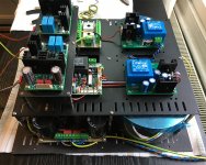
Ok understood. The idea behind my tinkering is to look at a relatively versatile supply that can supply a single channel's +ve and -ve rails at full rated power continuously or, if needed but not preferred, supply more than one channel. When I implemented astx's SA2014 200W 8R/400 4R amplifier I used his supply boards (and BoM), one supply for each channel (a dual mono block implementation within one enclosure). (I have attached a couple of pics of the early build stages.) His supply design uses 4 diodes to produce both +ve and -ve rails, i.e. in similar fashion to your RingNot PSU. With my question I was trying to get a sense as to whether people felt the extra four diodes were worth the space and hassle.
Attachments
Beware - there is a problem wih Mooly's simulation
After a long time ...
The connection between the negative voltage source and rectifier bridge is incorrect. This is what is causing the large transient at the start of the simulation and poor performance.
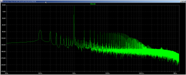
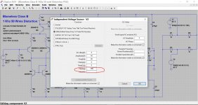
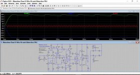
I modified the simulation to model a 160VA, 9% regulation 2x25V transformer and fixed the connection to the rectifiers. The results look much better.
See the attachments for spice screen and FFT when operating at 50W.
Have a look at this I cobbled together. Proper PSU (you would add any series resistance needed) and very small reservoir caps.
After a long time ...
The connection between the negative voltage source and rectifier bridge is incorrect. This is what is causing the large transient at the start of the simulation and poor performance.
I modified the simulation to model a 160VA, 9% regulation 2x25V transformer and fixed the connection to the rectifiers. The results look much better.
See the attachments for spice screen and FFT when operating at 50W.
Attachments
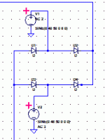
........... which is clearly not what Mooly was thinking.
Maybe Mooly wasn't thinking clearly 😉 It was just thrown together.
Tibouchina is correct. If you look at the ripple in a real dual rail supply then both halves mirror each other. I should have added a '180 degree' option to either of the voltage sources. Apologies for that.
Attachments
It's a good idea
😉 It was just thrown together.
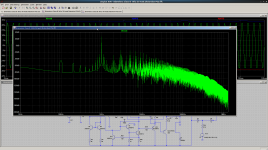
The basic idea is good (I tend to complicate things too much). It can be used to check the drop in rail voltages under load. The FFT shows a 100 Hz hum component about 110 dB down on 1 KHz tone at 50 W output.
I'm using the model with an Elliot P3A amp. It seems to match reality quite well. Have some more transformers coming in from local manufacturer Tortech. Want to do some measurements and improve the spice transformer model I plan to use.
One interesting thing to look for is a 100 Hz modulation of output audio when amp is clipping. I assume that wouldn't sound very good.

😉 It was just thrown together.
The basic idea is good (I tend to complicate things too much). It can be used to check the drop in rail voltages under load. The FFT shows a 100 Hz hum component about 110 dB down on 1 KHz tone at 50 W output.
I'm using the model with an Elliot P3A amp. It seems to match reality quite well. Have some more transformers coming in from local manufacturer Tortech. Want to do some measurements and improve the spice transformer model I plan to use.
One interesting thing to look for is a 100 Hz modulation of output audio when amp is clipping. I assume that wouldn't sound very good.
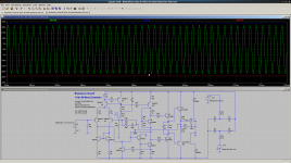
Amplifier clipping behaviour with Mooly's PSU Model
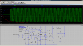
Well hopefully this will work.
When the amplifier is driven into clipping, the output waveform is amplitude modulated with a 100 Hz signal. This comes from the ripple on the rails. See the attached spice simulation results.
The FFT shows the 100 Hz ripple on the output has increased significantly and there are many intermodulation products. Does this mean the clipping will sound worse than if a regulated power supply was used? Don't know! Guess I'll have to do some real listening tests.
Another another concern is what happens when two amplifiers are attached to a common unregulated supply? There must be an interaction between the amplifiers.
Try attaching your pictures directly. They just show as page not found 🙂
Well hopefully this will work.
When the amplifier is driven into clipping, the output waveform is amplitude modulated with a 100 Hz signal. This comes from the ripple on the rails. See the attached spice simulation results.
The FFT shows the 100 Hz ripple on the output has increased significantly and there are many intermodulation products. Does this mean the clipping will sound worse than if a regulated power supply was used? Don't know! Guess I'll have to do some real listening tests.
Another another concern is what happens when two amplifiers are attached to a common unregulated supply? There must be an interaction between the amplifiers.
Attachments
- Status
- Not open for further replies.
- Home
- Amplifiers
- Power Supplies
- Incredibly dumb LTspice question: simulating amp load for PSU