
If wiring was not made short, if made twisted, it will oscilate.
I am sure about that, as i had this problem here, i love to twist my wires into transistor cables.
This practice, 40 years doing, cannot face sensitive amplifiers, the ones that have not Miller caps,...many times worst, when have not others capacitors installed dedicated to avoid oscilation.
To reproduce pure sound, the more simple use to be the better choice, with very rare exceptions.
Graham avoid capacitances inside the audio chain, this result is a very clear audio amplifier, but turns it unshielded related human errors.
All care must be taken related the wiring, each centimeter of lengh you can avoid will be better, parallel wires and small distance between wires must be avoided too...crossing wires are not so big problem..but keep all them as short as possible.
I had the problem, as i insist to twist my wires, something automatically done by me... resulted in hard oscilation, and during power on, i could heard RF beatings, crazy noises, alike SSB beating signals... sound turns crab (hehe), clipping in a strange way.... saturating awfully, power appeared reduced, as amplifier already near saturation with all those signals travelling with full power .. smell of resistor going to burn, transformer noise, result of excess of current...all those terrible effects...because of wiring.
Wiring was changed, and Doctor Graham was immediatelly informed... the actitude to remove the twisted wires result that i could remove my "protective caps" without problem.... zobel 2R2 is cold now, sound is very pure, a great amplifier.
45 years of experience, is not a guarantee of success, as a lot of mania... a lot of old uses we have, things that we do automatically..in other words... old guys foolishes (not all old guys included in this package) create the circunstances to some failures.... a human error to be kind to myself, in the reality, a more terrible effect .... agging.
No doubts, that Graham knows very well what he is doing, and the ones, alike me, that tried to "re-invent the whell", will have deceptive results.
Unfortunattelly, many will send to Graham, the responsability of their own errors, but now, he was clear to say the constructive skills needed... and he self protect himself against bad judgements
Thanks Graham.
regards,
Carlos
Hi John,
Thanks for your post.
Proper questions take the uncertainty away from me attempting to cover what others might be interested in.
You suggest some weakness under certain conditions; but the original JLH was just the same. JLH offered stabilisation suggestions, but they all affect back-EMf damping control and transient capabilities.
I have not had instability problems, and I never intended this amplifier to drive capacitors directly connected to the output terminals.
The fact that connecting 2uF without a normal length of cable could blow fuses, just like a direct short circuit will, does not concern me.
Many designers do not realise that they sacrifice coherent high audio frequency damping in order to claim unconditional stability.
My priority was to have good but relatively phase linear (resistive) damping, and this is what I have.
The original JLH class-A simulates with approx 30dB of mostly resistive damping, and Mauro's 'My "audiophile" LM3886 approach' in the diyAudio 'Chip Amps' section has approx 45dB, whereas the GEM has approx 75dB.
It is possible to have GEM-like circuitry suitable for driving electrostatics, but I wanted really good bass driver control and clean high energy treble for driving dynamic loudspeaker systems ... as delivered.
Electrostatics do not need to be driven by a high damping factor amplifier.
You ask if there is any way to compensate the second stage; but compensate = slow down = slower NFB generated control = affect hf damping control and accuracy of first cycle transient response.
Running this amplifier with 220k between output line and the VAS base reduces/levels the output stage gain without reducing capabilities, however there is then a reduction of negative rail common mode rejection.
As I said, there are many changes that can be made, but they all have their cost ! Also when it comes to determining stability the simulator does not match real life.
For driving electrostatics I would suggest a minimum 2m of cable and a 0.22 ohm series wirewound resistor at the live output terminal.
Hi Carlos,
I never did twist transistor wires together, but I have had oscillation on JLH variants by having wires wrongly positioned between pcb and heatsink.
I am sure some would comment that I should not have so wide a bandwidth, but the NFB loop has to work near instantly in order to maintain the good audio reproduction we have, and input filtering can affect differential NFB control too.
A cool Zobel is a good sign, so I hope all of your oscillation tendencies have now been covered.
Sure I am not a young thing any more either, and I too have been at this circuit for decades, but that does not automatically mean that my efforts are the best possible.
Cheers ........... Graham.
Well, made with short wires and worked fine.
Till i decided to reduce a little the bias, and adjusting i turn trimpot to the other side.... Plaft!...gone the extra transistor, the extra NPN, the control transistor.
I advance too much it's VBE, and that one, beeing a fake TIP35, could not accept 15 amperes...gone!
So, having not the same stile transistor, only TO-3, i decided to make changes, to see how tollerant this schematic will be to modification.
I changed the bias current, the bootstrap condenser, removed the bias adjustment trimpot and auxiliary bias transistor...the VBE multiplier....hummm, very sophisticated name to a variable resistor, and put it into work again, now around 700 miliamps when hot.
Sounded very good..i am hearing it now, will go observing the differences .... first hearing told me nothing different related the GEM, non modified, amplifier.
Of course will be different, but i will need some time to find those differences.
Oh, i was forgetting, the input transistors were substituted by BF422 and BF423.
regards,
Carlos
Attachments
Negative, this modified not aproved, it works but related to details...negative!
Hearing woman singers, making back vocal to Pepino di Capri in Concert, i could not heard the girls separated.... their voices were mixed in on resultant voice.... even making efforts, could not hear.
I tried headphones and increase 1K to 5k in the equalizer, to have better female voices.... i cutted the bass also but could not perceive, as i was perceiving with GEM, and many others.
Detail, focus not good.
Noise was better, as my computer board is noisy, and i changed input transistor with 340 gain for 150 gain units....lower noise resulted...but if you increase volume..there's the computer noise...but, at normal listening levels (around 2 watts average). i could not perceive any noise..... as i perceived before.
This loss of detail killed my modified unit...will return to original GEM.
The circuit is tollerant to modifications, the audio result is not.
regards,
Carlos
Thanks DX, you are really helping out those of us who plan to construct this amplifier...
...after you tell us how you blew it up a few times, we will know what not to do.
But seriously, thanks for reporting back all these findings for us.
...after you tell us how you blew it up a few times, we will know what not to do.
But seriously, thanks for reporting back all these findings for us.
Stocker, i think now is clear, the reason why my nick name is Destroyer eXtra.
Very common here, to destroy transistors.
My incidence of fails are big, also the number of things constructed
I am still studying, to discover, if i burn so many transistors because i construct many amplifiers....or, more realistic, if i construct many amplifiers because i blew the last one transistors.
Yes, i normally use protective resistors...but...to make small adjustments when the amplifier was already done days ago, i do not use them, so....Pláft!
regards,
Carlos
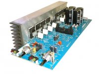
This is the "non aproved" amplifier, the modificated one.
Graham will be shocked with the wires length....
Oh dear Carlos, can't you see capacitance there?
- Yes Graham, i can see, will use some "L" shape aluminium, to bring transistors more close to the board, this way, wiring will reduce from 50 milimeters length into 15 milimeters length.
- He disappeared...so shocked he is.
Some images of the non aproved unit will be posted hear..even non aproved, can kick many amplifiers with pretty Industry Brand names on it..without any effort!
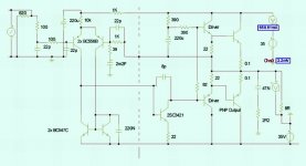
This one is something to construct to hear...but be prepared with 10 to 50 pf capacitor to put as Miller, over the voltage amplifier, as i made three constuctions, and this one needed the Miller.
The first and second constructions, did not need the Miller unit..i turn crazy with those things, the first one, had 25 centimeters of twisted wires...and nothing oscilated, and used a very sensitive transistor as Voltage amplifier.
Well guys, I have a long way to go..have many things to learn and understand...and this is GREAT!
regards,
Carlos
Graham will be shocked with the wires length....
Oh dear Carlos, can't you see capacitance there?
- Yes Graham, i can see, will use some "L" shape aluminium, to bring transistors more close to the board, this way, wiring will reduce from 50 milimeters length into 15 milimeters length.
- He disappeared...so shocked he is.
Some images of the non aproved unit will be posted hear..even non aproved, can kick many amplifiers with pretty Industry Brand names on it..without any effort!
This one is something to construct to hear...but be prepared with 10 to 50 pf capacitor to put as Miller, over the voltage amplifier, as i made three constuctions, and this one needed the Miller.
The first and second constructions, did not need the Miller unit..i turn crazy with those things, the first one, had 25 centimeters of twisted wires...and nothing oscilated, and used a very sensitive transistor as Voltage amplifier.
Well guys, I have a long way to go..have many things to learn and understand...and this is GREAT!
regards,
Carlos
Attachments
Because appearance, because fail somewhere in audio reproduction, the normal decision
Is comdemned the unit to death or dismount (better because of Sankens).
But the pictures cannot show you the sonic results.... but i can tell you some idea...It is a big Power DOZ, with wonderfull bass response...and off course, better dinamics and higher speed...even defective in audio focusing. (This unit guys, not the Graham design)
More images.
regards,
Carlos
Attachments
No, i will not dismount, will fix it, returning circuit to original... here to stay.
Will fix this one.
Have beautifull sonics when perfect.
Aksa for treble, GEM for low frequencies, mids and low mids, and 250 watts Symassym to sub woofer bass... hard to beat this system.
regards,
Carlos
Will fix this one.
Have beautifull sonics when perfect.
Aksa for treble, GEM for low frequencies, mids and low mids, and 250 watts Symassym to sub woofer bass... hard to beat this system.
regards,
Carlos
Attachments
Hi Carlos,
I'm doing some catching up here. Post#144.
Great to see you trying slightly different circuitry, though I would never experiment without resistors in the psu rails to limit current long enough for the fuse to blow.
Don't forget that it is the series bootstraped resistors that set the VAS/splitter collector current, and so any changing of the values here will also change the Vbe for the class-A output transistor. If you changed from 390+820 to 390+390 then you increased driver current from approx 28mA to 43mA; so the class-A bias resistor would have needed to be adjusted down by 35% (approx 22 to 15 ohms) prior to power-up - or - Plaft!
The Vbe multiplier invertedly amplifies the temperature induced bias voltage change across itself to match that of the output transistors it feeds. When mounted on the heatsink this allows its generated bias voltage supply to compensate for increased current draw by hot class-AB power transistors.
I don't think the 22pFs at the input would be big enough to filter digital/RF noise. I used 220pFs and assumed cable capacitance with a proper pre-amp/audio/portable CD source. Capacitors at the differential input don't just filter source input but can affect how the NFB loop is able to control high audio frequency resolution.
I'm now up to downloading your mini-pics from post 148 onwards, and will come back shortly.
Gee. Look what happens when you send Carlos a circuit.
He studies it from every angle, including inside-out, which as you say Stocker, is to everyone's benefit - including mine - which is why I send them !
Cheers ........ Graham.
All message very clear received Graham
That "plaft" you said, i have enormous expertise in that area.
Some make "Thaftthisss".... other only a "poc", but all noises are result of foolishes made.
Yes, i made modifications, and perceived that had to reduce driver emitter resistors (used 10 ohms)....but do not know why the 22ohms returned to it's place..do not remember, maybe too much difference in Vbes related output and driver.
Yeah!, there are normally, sligth difference between driver and output VBEs...as current is also different... the colector to emitter current, but i perceived that the difference obtained was bigger than normal.
I did not show you, but i had to install a 10N capacitor (103) in the input, in parallel with 620 ohms, result of high noise that my computer produces, it is a on board audio chip model, a hissing one.
I remember that VBE is used to control temperature drift, but i am using enormous heatsink with a fan pumping air across it.... too much cold, even full power over 8 ohms, to use the VBE multiplier...in its place an adjustable resistor, a trimpot, that i will substitute for a fixed resistor...i tried diodes too, but had to use a trimpot in parallel to adjust...as the trimpot was needed, well, decided to left the trimpot already there, to avoid diodes plus trimpot...i prefered the trimpot that will be substituted by a fixed resistor.
The input is using hi speed transistors, also VAS, drivers and output.... but using computer as audio source, no difference..had to install an Aiwa portable CD player, with your test CD to perceive all the beauty in the trebles range.
The test CD has humble... a long time passed in my life, without observe that effect, but could not perceive vinyl noises, but very low frequency humble was clear with good amplifiers that could reproduce 5 to 8 hertz....interesting!
Confirm please, if that test CD was produced from a turntable source.
regards,
Carlos
Hi Carlos,
Shocked ? Not at all.
In fact I applaud you for trying it like this.
You can change anything to try out an idea, or go through a whole range of component values and different types to see which 'sounds' best.
This way teaches so much, but then if someone builds it differently to yours, it might perform differently !
Okay, so it needed a Miller C.dom.
Much better knowing you could do that, than not have anything working at all.
One of the reasons I don't like Miller C.doms with class-AB is because their hf current draw from the input stage is non-linear at the point where there is a sudden collector voltage swing through the class-AB voltage bias range that becomes necessary when the output current is phase shifted by a real loudspeaker.
There is a narrow range of circuit related values at which the C.dom can have a beneficial effect, but beyond that it starts to affect hf audio.
The capacitor should also be very high quality; ie. not ceramic.
Good to see your progress and I would be very pleased to read your final conclusions from this work in progress.
I have not had a chance to try anything more with mine since I drew out the circuit. Maybe soon.
That test CD is not from vinyl. There are some genuinely low frequencies on it, but sometimes the Analogue>Digital process also induces sub audio error and this gets coded onto some tracks.
Most 'normal' systems are completely deaf at these frequencies though !
Cheers ........ Graham.
My constructions related GEM are ended, and very happy with this amplifier.
The circuit is the original one, no modifications needed.
Well...maybe a small cap in the voltage amplifier, but this will depend of your construction.
regards,
Carlos
The circuit is the original one, no modifications needed.
Well...maybe a small cap in the voltage amplifier, but this will depend of your construction.
regards,
Carlos
Hi Carlos,
I am surprised it works with such long wires, but I am not too old to learn !
Now all I need is the temperature controlled fan, for slow when cool, and fast when hot.
Cheers ......... Graham.
I am surprised it works with such long wires, but I am not too old to learn !
Now all I need is the temperature controlled fan, for slow when cool, and fast when hot.
Cheers ......... Graham.
Believe it or not, it worked with 20 centimeters of twisted wires too
And 3 wires twisted to each TO-220 and to output.
Each one of them with 25 to 20 centimeters, each transistor with the result "cable" of twisted wires.
I use to do that with many amplifiers, and not common to face problems of oscilation, because of that...when or if oscilation started, the first actitude is the twisted cable remotion...better to be ugly (not twisted) than oscilate.
The ones that oscilate with twisted, also oscilated with non twisted too.
The conection between this capacitance and oscilation is theoretically proved...but in practice.... it works!
Well....maybe my twist is very special....i use an battery powered electric drill machine to twist them...when too small, i twist them with my hands.
The electrical result is one capacitor from base to emitter, other equal from base to colector, and other equal from colector to emitter...remember...very distantly, a Wien bridge.
those amplifiers, that we put the finger in the input pin, and start to receive radio frequencies, or start to heat the zobel, or produce some noise audible, because board and parts ressonances...those ones..will oscilate with long, short, twisted, and shielded wires. (more easy to oscilate when twisted..in theory).
Related the inductance, caused of wire length or even wire bending, forming a half turn coil... tunned to several megahertz, you can see one automobile amplifiers, with jumpers connecting transistors..long wire jumpers.... see the picture attached.
Symassym 4 use twisted wires too...cannot show you, as my pen foto machine was damaged by my small daugther.... ahahahah, you are all free from my awfull pictures.
regards,
Carlos
Attachments
Hi Destroyer X,
Carlos what is the purpose of showing the photo of assembly module of qsc rmx amplifier.......
K a n w a r
Carlos what is the purpose of showing the photo of assembly module of qsc rmx amplifier.......
K a n w a r
Kanwar, observing the assemble, i had the idea that it is using long jumpers, and it
is possible, that some of them have audio signal passing...so... long lengths or wire, even beeing dangerous to produce parasitic oscilations, are used and can work fine in many amplifiers.
I could see some Panasonic Systems, using 2 inches long jumpers connected to power amplifier input.
If you can inform this unit construction details, to confirm or dennie my argument...please, use this space, our forum.
That's the reason why Kanwar.
regards,
Carlos
No , No Carlos these are not jumpers these are welcome greetings to Mr.Parasitic Oscillation Man.....😀 😀 😉
K a n w a r
K a n w a r
Ahahahaha!...very good mood Kanwar
Invitation posts to parasitic oscilations was great!
regards,
Carlos
Invitation posts to parasitic oscilations was great!
regards,
Carlos
- Status
- Not open for further replies.
- Home
- Amplifiers
- Solid State
- Incredible quality amplifier by Graham, prepare your ears for it