So there is no a general rule about optimum bias setting.
And the only method is to perform distortion tests in order to find the value of bias current at which the crossover distortion is minimum.
Nice to see that this is possible, with some topology, with low bias current (i.e. 22mA).
Very interesting.
Thank you very much and kind regards,
beppe
And the only method is to perform distortion tests in order to find the value of bias current at which the crossover distortion is minimum.
Nice to see that this is possible, with some topology, with low bias current (i.e. 22mA).
Very interesting.
Thank you very much and kind regards,
beppe
Hi Mike,
I am only monitoring the residual output of a standard THD meter. A Leader LDM-171 in this case. There are far superior instruments I'm looking at to extend my range and understanding.
Driver operating points are set with fixed resistors. So our lowest distortion setting will measure everything. That's another kettle of fish.
-Chris
Maybe there is PC software available to do that via soundcard ?
This feature to view the residuals is very helpful as it shows the kind of distortion, difficult to see in fft plots.
I was aware of a bias where crossoverdistortion for ClassAB is lowest, but would never have expected it at 22ma for the MJW0281/0321.
Mike
This feature to view the residuals is very helpful as it shows the kind of distortion, difficult to see in fft plots.
I was aware of a bias where crossoverdistortion for ClassAB is lowest, but would never have expected it at 22ma for the MJW0281/0321.
Mike
AndrewT said:my enquiry
www.diyaudio.com/forums/showthread.php?postid=996268#post996268
If i posted on that thread that i agree with the reasoning i'd have Ace on my back again for Prof. bashing.
Another point is that Hfe linearity of med. power devices such as the MJEs sucks at low emitter currents.
Hfe-I curves on datasheets that start at considerable output currents raise an eyebrow or two, resembling statements at a conference that the question is very interesting but too complicated to answer in a mere few minutes.
The driver A to B crossing is at a 0.7 volts output level distance from the output stage zero crossing, driver bias level is unlikely to matter much there.
In low impedance loads the output current can increase untill there is an additional 0.7 volt drop across the output device RE's before the driver crosses. Higher driver bias keeps that region more linear. An ESL has it's impedance weakpoint at the higher frequency range, makes one wonder why a simple circuit as that of the KSA is such a decent mate, surely not just because the output stage is class A biased.
A book by Gere and Timoshenko is the standard mechanical engineering textbook at universities of technology around the globe for civil engineers, mechanical engineers, aerospatial guys and turds of other disciplines. Fat one, the type that makes you place formula filled notes on every wall for memory sake.
Jacko, i don't know to which MJE devices you refer, but i've measured MJE15030/31 with hfe > 100 at 1ma...
I have no idea why the datasheet for a driver transistor starts at 100ma... 🙄
Mike
I have no idea why the datasheet for a driver transistor starts at 100ma... 🙄
Mike
Hi Mike,
I've seen it lower with some designs. If we reduced the value of R26 (33R), the drivers would be biased a little harder on.
I will try to run this on my sound card. They are about 20' apart with mountainous territory in between.
-Chris
I've seen it lower with some designs. If we reduced the value of R26 (33R), the drivers would be biased a little harder on.
I will try to run this on my sound card. They are about 20' apart with mountainous territory in between.
-Chris
Chris, the drivers are biased with ~40ma, this should be enough to keep driverstage permanently in ClassA.
Replacing the 33ohm with a ccs might be even better...
Mike
Replacing the 33ohm with a ccs might be even better...
Mike
MikeB said:idea why the datasheet for a driver transistor starts at 100ma
Specs consistency.
If you can not guarantee minimum specs, skip them.
MJE1503* datasheets look pretty decent for the power level they offer. A relic like me remembers output stage devices that didn't have such high continuous output currents.
Doesn't mean they look terrific compared to a number of Japanese driver devices that offer a straight line from 10 to 100mA. Is it that interesting what an "Audio" driver does at 100mA or higher ?
Hi Mike,
You may be getting away from the pure sound of a resistor <ducking and running for cover! 😀 >
Have you tried to reduce the bias on yours? Give it a shot and let me know.
-Chris
Voltage compliance. Two words that can be so depressing. That would be an interesting experiment.Replacing the 33ohm with a ccs might be even better...
You may be getting away from the pure sound of a resistor <ducking and running for cover! 😀 >
Have you tried to reduce the bias on yours? Give it a shot and let me know.
-Chris
Will try tomorrow... Have to change back a lot of other changes...
"Pure sound of a resistor"... That's a good one !
Voltage compliance ? No, not depressed, replacing the 33ohms with a single jfet does the job. 😀 Sims say: drivers bias reduced to 12ma with slightly improved quality, but no real benefit.
Mike
"Pure sound of a resistor"... That's a good one !
Voltage compliance ? No, not depressed, replacing the 33ohms with a single jfet does the job. 😀 Sims say: drivers bias reduced to 12ma with slightly improved quality, but no real benefit.
Mike
Hi Mike,
Don't forget to reduce your bias current and have a listen. 22 mA.
-Chris
Use two, they're small. 😀 Should get you up to 24 mA.Sims say: drivers bias reduced to 12ma
The wire guys would be all over "slightly improved". Like lifting a veil.slightly improved quality, but no real benefit.
Don't forget to reduce your bias current and have a listen. 22 mA.
-Chris
anatech said:The wire guys would be all over "slightly improved". Like lifting a veil.
double-😀 !
Yes, i will try the 22ma bias tomorrow.
I once tried different biasings, below 10ma the sound became harsh, did not really perceive benefit in higher bias up to 100ma and then simply kept the ~50ma.
Mike
MikeB said:double-😀 ! ... I once tried different biasings, below 10ma the sound became harsh ...
Mike
This is very interesting to me because "rumors" are that the bias in my amp is set exaggerately low.
And actually I am experiencing some harshness in sound.
At this point a bias check is just mandatory I believe.
Thank you very much and kind regards,
beppe
Hi Beppe,
have you checked the output stage bias at various temperatures?
i.e. 1. at a few seconds after start up (cold).
2. at a few minutes after start up (slightly warm)
3. after many minutes after start up (fully warmed up)
4. immediately after playing some very loud music (the output stage running very warm).
5. while artificially heating the sink with an external heatsource eg hairdryer.
The minimum bias in any of these conditions is crucial.
The variation in bias with changes in temperature will make it more difficult to set up the amplifer to sound good in all operating conditions (i.e. indicates a poor design).
AndrewT said:Hi Beppe, have you checked the output stage bias at various temperatures?
i.e. 1. at a few seconds after start up (cold).
2. at a few minutes after start up (slightly warm)
3. after many minutes after start up (fully warmed up)
4. immediately after playing some very loud music (the output stage running very warm).
5. while artificially heating the sink with an external heatsource eg hairdryer.
The minimum bias in any of these conditions is crucial.
The variation in bias with changes in temperature will make it more difficult to set up the amplifer to sound good in all operating conditions (i.e. indicates a poor design).
Thank you Mr. Andrew for your very kind and valuable advice.
1) Until now I have only looked inside without checking/setting anything.
I have only heard rumors about a bias of about 6 mA (i.e. very low).
By the way I can attest that the amp remains cold even after left on for an entire day. So the bias should be very low really.
Not even warm.
I think I will have my amp serviced in the next days for a bias checking an maybe try a 20 mA new setting while monitoring the temperature trend on the heatsinks.
Thank you very much and kind regards,
beppe
Hi Beppe,
if you ask the Technician to reset the output bias and not check for evidence of overheating and/or thermal instability, then you are asking for trouble.
If you ask the Technician to reset the output bias and check the effect over a range of operating conditions then you are going to get a big bill for all his time.
I suggest you ask him to check and reset, if necessary, to the manufacturers specified output bias and ask his advice on the efficacy of increasing the bias for this particular amplifier.
beppe61 said:remember an amp where the output stage had separate supply and acted as unity gain buffer with the driver stage powered by an independent power supply.
Example:
the Audiolabor Stark monoblocks from the first half of the 80s, around 200 watts/8 continuous from 3 pairs of Sanken 2SA12/SC29 RETs.
The separate powersupplies for driver and output stage was not done for independant biasing purposes however, but to cancel out intermodulation between the two.
Like some circuits floating around overhere the Stark output stage did not have voltage nfb, to cancel out additional distortion due to back emf. (no output stage nfb lead to a distortion figure in the 0.2-0.4% range)
See picture: separate capacitors and transformer windings, the 2 blue caps are for the driver stage.
Attachments
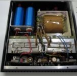
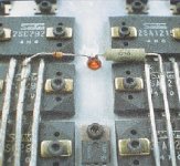
If you like watching output stages, the one of the Stark=>
Look Ma, silver hookup cable in 1982 !!
(the little golden washers under the bolts are great for torqueing, i can post a pic of one if desired)
Scuse the pic quality, my picture resizing software is acting up again.
Look Ma, silver hookup cable in 1982 !!
(the little golden washers under the bolts are great for torqueing, i can post a pic of one if desired)
Scuse the pic quality, my picture resizing software is acting up again.
Attachments
jacco vermeulen said:
Example:
the Audiolabor Stark monoblocks from the first half of the 80s, around 200 watts/8 continuous from 3 pairs of Sanken 2SA12/SC29 RETs.
The separate powersupplies for driver and output stage was not done for independant biasing purposes however, but to cancel out intermodulation between the two.
Like some circuits floating around overhere the Stark output stage did not have voltage nfb, to cancel out additional distortion due to back emf. (no output stage nfb lead to a distortion figure in the 0.2-0.4% range).
See picture: separate capacitors and transformer windings, the 2 blue caps are for the driver stage.
Very remarkable amp indeed.
Thank you for the pictures. Very interesting.
I feel it is a great sounding amp.
Regards,
beppe
pm7200 schematic
hello
i m interested in the schematics of the marantz pm7200. just to see what can be improved (and to see if there is an input cap ti prevent from dc offset so that i can remove the one in my cd5001 cd player.
thanks
hello
i m interested in the schematics of the marantz pm7200. just to see what can be improved (and to see if there is an input cap ti prevent from dc offset so that i can remove the one in my cd5001 cd player.
thanks
- Status
- Not open for further replies.
- Home
- Amplifiers
- Solid State
- Increasing bias in amps.