162.7 - 71 = 91.7
163.2 - 71.3 = 91.9
On 100V rated capacitors.
Close to the limit, safe for the time being as they are good quality.
Try and put some sort of over voltage control, MOV is the most basic, to keep your unit protected.
As a spike buster too, MOV or transient voltage suppressors are good practice with expensive equipment.
Before you mount the new 4-legged ones on the original PCB, you might want to double check -- IIRC the extra 2 legs must remain unconnected! Not sure whether that requirement applied to this exact p/n (worsening memory, anybody .. 😱), but noticed it while looking up candidates for this replacement.
Cheers
Cheers
Mate, yes I should have. Should have also left good enough alone. But I’m not real good at that.
I measured the two extra pins in every direction and they seemed unconnected electrically so I though what the hell and punched them in for the extra stability. Obviously not so clever.
The kids had a ball. “Look dad blew up the amp!” Some real life lessons in that for the whole family. My mrs had some choice words. I learn to conduct fire-up tests in the shed……
Attachments
Thank you.
> “Look dad blew up the amp!”
I always say, "Pictures or it didn't happen!!" You got the picture.
> “Look dad blew up the amp!”
I always say, "Pictures or it didn't happen!!" You got the picture.
Impressive, I particularly like that you took the trouble to get a good picture at what must have been a stressful time... 😀Mate, yes I should have. Should have also left good enough alone. But I’m not real good at that.
I measured the two extra pins in every direction and they seemed unconnected electrically so I though what the hell and punched them in for the extra stability. Obviously not so clever.
The kids had a ball. “Look dad blew up the amp!” Some real life lessons in that for the whole family. My mrs had some choice words. I learn to conduct fire-up tests in the shed……
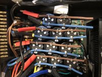
Pulled the damn caps off the board again and hooked them up via fly wires. Ready to plug back in on the morrow. I can’t believe this thing still measures like it will work if the caps hold. Without the caps (amp section not connected) the dc rails measure -107.1 -46.8 +47.2 +107.8. The ac coming off the Trafo measured 125 and 55 per usual. The rectifier bridges pass current as expected, at least unchanged to what they did before the fiasco.
Channeling Dustin Hoffman: Is it safe?
Also, I’m now one cap short. Should I put one of the old ones in or just try with 11 little friends? Does it matter if one rail is off by 33% capacitance compared to the others?
Channeling Dustin Hoffman: Is it safe?
Also, I’m now one cap short. Should I put one of the old ones in or just try with 11 little friends? Does it matter if one rail is off by 33% capacitance compared to the others?
Attachments
I would check all the caps, and leave one out on the other rail, to maintain symmetry.
And use it on lower power.
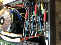
But if the extra pins on the caps were not connected, what made one blow its gasket, as it were? You said you punched them through, as a support that is fine...
The right top cap in the picture has a blackened extra pin...please check.
And use it on lower power.
But if the extra pins on the caps were not connected, what made one blow its gasket, as it were? You said you punched them through, as a support that is fine...
The right top cap in the picture has a blackened extra pin...please check.
Last edited:
This is the second amp that blew up to my knowledge in the past few days, another did its transformer, transistors and speakers in Hyderabad...8 x 5200/1943 pairs, 700 VA toroidal main transformer, and did that after working well for several hours after assembly.
It had been a back burner project for several years.
It had been a back burner project for several years.
The caps all hold charge. I don’t have a decent meter for capacitance etc.
The additional holes mentioned earlier went through the circuit board so would have connected to the rails. On one cap i did measure conductance between one of the support pins and a live pin but now they are not connected can it harm? On all the others the support pins are isolated. I get what you’re saying about symmetry so might take that one off again.
The additional holes mentioned earlier went through the circuit board so would have connected to the rails. On one cap i did measure conductance between one of the support pins and a live pin but now they are not connected can it harm? On all the others the support pins are isolated. I get what you’re saying about symmetry so might take that one off again.
Remove the black cap one as a suspect one.
Take one from the other rail as symmetric.
But any cap that has seen catastrophic failure on the rails is suspect as having a damaged structure, so long term please replace with 200V units, 105 degrees...expensive.
I wonder how motor running capacitors would work as reservoir capacitors in a power supply...much cheaper than these.
A capacitor that has had a neighbor burst is suspect in many ways, reduced life and increased chance of failure are to be expected.
And the next failure may not be so pretty or safe.
My advice: Get new ones, and shift these to the lower voltage rail after checking them.
Here a graphic type capacitance meter (it has a 128 x 64 dot display) is only about 10 US dollars, and apart from capacitance, it has many other functions, you need to make a housing, it comes as an assembled board running on a 9V battery.
See it on robu.in..
You might find it on other sites too.
At that price, it seems worth it.
Isn't the one that spilled its guts already one of the ones on the lower voltage rail?
With 3 of them identically connected and only one failure -- plus the outgassing from the top, instead of the designed vent -- I'd be tempted to take it up with the vendor. Digi-Key might just send you a new one, free! 😀
Although thorough testing is always fun and reassuring, and sometimes revealing, it doesn't always prove which part will fail in circuit.
Cheers
edit: Plus, you have a great picture!
I wonder why they provided extra supports, and whether they are some sort of shield for RF suppression?
In that case they would be sold as such.
He has not explained why he connected them to a rail, by choice or chance.
In that case they would be sold as such.
He has not explained why he connected them to a rail, by choice or chance.
Ok. Wow. She works. And that’s in spite of my ineptitude.
I put the caps on rails because the circuit board is rooted after I drilled the extra holes for the extra legs on the caps. Which was stupid. As we now know.
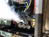
I then took all the caps off the board and put them on four rails. It worked. It had a hum. I had another look. I took the board off before discharging the caps. A flashbang later and the 24v circuit which happened to make the connection between what must have been several hundred volts and ground blew up. Diodes burst, traces on the circuit board melted. I swore.
Pulled the whole crapola out and painstakingly (lovingly?) replaced diode and put jumpers where the traces were. Hooked her up using a 50w incandescent in series (also good to have on hand to discharge caps….) and she fired up. Sounded super crap. Voltage reading on the 24v rail too high. Just about to order a regulator thinking that had also blown then thought what the hell and tried without the light. And it’s good! The 24v rail reads 36v. But all that seems to impact is the speed of the fans and the speed with which the protection relay engages (faster).
Tomorrow I’ll let her run for some hours in the shed, see if she blows again. Here a photo of a bodgy job if there ever was one.
If the job holds I may redo the entire power board. I feel I owe it to the amp.
I put the caps on rails because the circuit board is rooted after I drilled the extra holes for the extra legs on the caps. Which was stupid. As we now know.
I then took all the caps off the board and put them on four rails. It worked. It had a hum. I had another look. I took the board off before discharging the caps. A flashbang later and the 24v circuit which happened to make the connection between what must have been several hundred volts and ground blew up. Diodes burst, traces on the circuit board melted. I swore.
Pulled the whole crapola out and painstakingly (lovingly?) replaced diode and put jumpers where the traces were. Hooked her up using a 50w incandescent in series (also good to have on hand to discharge caps….) and she fired up. Sounded super crap. Voltage reading on the 24v rail too high. Just about to order a regulator thinking that had also blown then thought what the hell and tried without the light. And it’s good! The 24v rail reads 36v. But all that seems to impact is the speed of the fans and the speed with which the protection relay engages (faster).
Tomorrow I’ll let her run for some hours in the shed, see if she blows again. Here a photo of a bodgy job if there ever was one.
If the job holds I may redo the entire power board. I feel I owe it to the amp.
Attachments

But I wouldn't run it beyond a brief test with 36V on the 24V supply. The fact that nothing blew instantly doesn't imply that it is O.K. with it. The relay coils are probably doing a slow heat buildup, for example.
Maybe this would be a good time to install bleeder resistors on those high capacity banks. Good practice dictates it, anyway.
Cheers
Last edited:
- Home
- Amplifiers
- Power Supplies
- Inconsistent voltage after rectifier