Hello - I'm a bit baffled by a no-load test on swapping the input/output on a small power transformer: 'Been doing electronics for years, but never had occasion to feed the secondary, versus primary, to get (modest plate current) HV B+ from surplus former transistor amp xformers...
In slowing ramping up the input voltage to this ~2Ampere 24vac xformer (e.g. 5:1 ratio), I was not able to get even 20vac into it - e.g. 100vac out - before it began overheating; again...no-load?!?
I regularly see 120->12->120 small ampt PS's ...but, are there some (unusual?) windings on standard power transformers that would preclude pushing them backwards - e.g. heating up on their own eddy currents? Thanks in advance for any practical experience and findings...!
The convention for a transformer windings is just this: a convention. In real world, any winding may be the primary (only one at a time) while other(s) may be the secondary(ies).
But there may be some differences. For example, a 220V to 24V AC transformer, when feeding the 24V winding may give 200VAC in the other winding, because sometimes the "primary" has a bit less turns and the "secondary" a bit more in order to compensate losses in winding resistances.
But there may be some differences. For example, a 220V to 24V AC transformer, when feeding the 24V winding may give 200VAC in the other winding, because sometimes the "primary" has a bit less turns and the "secondary" a bit more in order to compensate losses in winding resistances.

The main problem is the regulation: for example, a 230V-->24V 10VA transformer is in fact a 230V -->30V, no load. With a 10VA load, it will deliver its nominal 24V.
It also works in the opposite direction: with 24V at the secondary, it will deliver 190V on the primary, under no-load conditions. When loaded, it will deliver 170V or even less
It also works in the opposite direction: with 24V at the secondary, it will deliver 190V on the primary, under no-load conditions. When loaded, it will deliver 170V or even less
The secondary of a step-down transformer will have less inductance and resistance so the transformer's idle current will be much higher when the secondary is connected to AC line, and the core will saturate.
No. If you apply to it proper voltage, it will not saturate.The secondary of a step-down transformer will have less inductance and resistance so the transformer's idle current will be much higher when the secondary is connected to AC line, and the core will saturate.
Nobody in this thread is doing that. Why suggest it?120VAC is applied to the 24VAC secondary.
To clarify, I had every reasonable expectation to slowly increase the voltage to the (as-designed) secondary, with the primary delivering 5x the applied ac voltage from the variac. I was shocked to overheating at less than half of line voltage - absent any load. I would still appreciate a technologically thorough explanation of why (at SUBSTANTIALLY less than any hipot test voltage) this occurred... THX
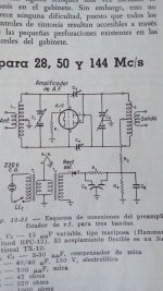
Or the transformer is really bad designed/built. The idea of using a transformer to increase heater voltages for low current stages or for bias has been in use from decades ago. Here is one taken from a ARRL Handbook 1954 in Spanish.
Attachments
Last edited:
Good thoughts - but with the source being a simple variac following an iso-trans, I'd be at a loss where rectification of any sort could occur. I'll try a few more small xformers just to satisfy my curiosity (and for fun, monitor on the scope <'good call>). 'Might have a chance to do some scholarly research this weekend. Hmmmm
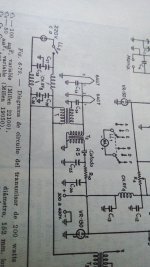
In English:another example from the same book but 1952 edition.
https://worldradiohistory.com/BOOKSHELF-ARH/Bookshelf_ARRL.htm
Note they changed the 115VAC to 220 v. c.a.
Also note the rectifier is "drawn backward". There was some confusion the first few years.
- Home
- Amplifiers
- Power Supplies
- Inability to "reverse" (backfeed/step-up vs step-down) small transformer <?>