Wow, thanks for posting. So all of the agnds go to the same pin? I wonder which transistors would work well in this cicuit and not overheat, especially since they wont be able to dissipate most of their heat into the board like the originals?
it appears that most dissipation is done by the last four transistors Q4, Q8, Q9, Q10 and the rest is having an easy time. from what I can tell.
I was planning on using through hole parts to have higher dissipation ratings.
I was planning on using through hole parts to have higher dissipation ratings.
djQUAN nice card you made. The issue of thermal stability will show up as DC offset and drift. PPI went with this Ceramic driver card for lots of reasons, one of which was thermal tracking.
The other was modular design with ease of repair at PPI's repair facility.
PPI used these for years in most all upper models above 50 watts per channel and above. It reduced parts count and assembly time.
The CZTA42/92 parts were used for their high voltage capability as these boards will see up to 60 volts +&- on larger PPI amps. I hope the BD-139.140 setup will work well for you. I would be interested in your results and findings with those devices.
Nice work, you don't fool around time wise 🙂 And I think you will find that going with the original design will save you tons of time and issues later on, I did....🙂
1moreamp said:djQUAN nice card you made. The issue of thermal stability will show up as DC offset and drift. PPI went with this Ceramic driver card for lots of reasons, one of which was thermal tracking.
The other was modular design with ease of repair at PPI's repair facility.
PPI used these for years in most all upper models above 50 watts per channel and above. It reduced parts count and assembly time.
The CZTA42/92 parts were used for their high voltage capability as these boards will see up to 60 volts +&- on larger PPI amps. I hope the BD-139.140 setup will work well for you. I would be interested in your results and findings with those devices.
Nice work, you don't fool around time wise 🙂 And I think you will find that going with the original design will save you tons of time and issues later on, I did....🙂
Note that you might be able to reduce thermal tracking issues by reducing the degeneration resistors (R1-R4) a bit - say to 270 ohms.
1moreamp said:djQUAN nice card you made. The issue of thermal stability will show up as DC offset and drift. PPI went with this Ceramic driver card for lots of reasons, one of which was thermal tracking.
The other was modular design with ease of repair at PPI's repair facility.
PPI used these for years in most all upper models above 50 watts per channel and above. It reduced parts count and assembly time.
The CZTA42/92 parts were used for their high voltage capability as these boards will see up to 60 volts +&- on larger PPI amps. I hope the BD-139.140 setup will work well for you. I would be interested in your results and findings with those devices.
Nice work, you don't fool around time wise 🙂 And I think you will find that going with the original design will save you tons of time and issues later on, I did....🙂
I chose the BD devices for their current and dissipation capabilities. the amp I'm fixing is 100wrms X2 so that would only be about +/-35V. for higher rails, I would think MJE340/350 pair should work. 🙂
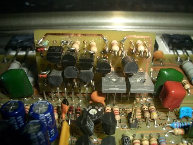
I hope making the board very compact and placing all transistors side by side helps with thermal tracking.
EnvisionAudio said:
Note that you might be able to reduce thermal tracking issues by reducing the degeneration resistors (R1-R4) a bit - say to 270 ohms.
I'll try that if I have issues with stability.

had the time to make the replacement cards last night and plugged one in just now.
the ones I made last night are exactly as the schematic I posted except for the 125k resistor. didn't have any in stock so I used 150k.
the amp powers up, and makes nice clean sine waves right away without any adjustments.
DC offset is 40mV.
will install the card for the other channel in a bit.......
something is not right. something is supposed to go wrong at first power up when I build/make something.....
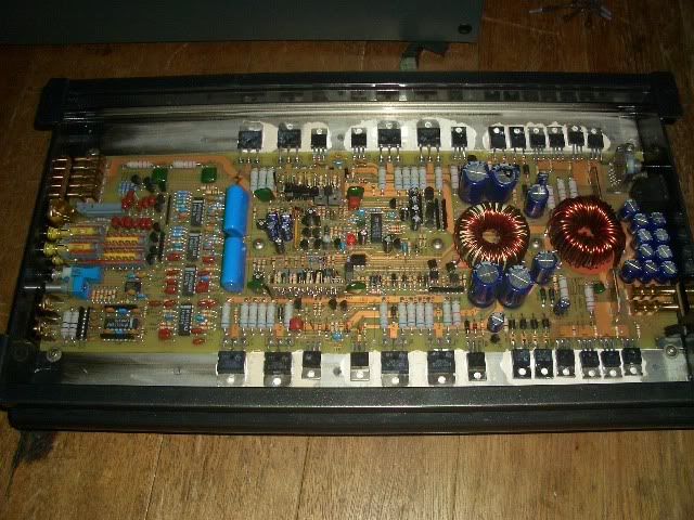
installed both modules and it works perfectly.
was able to adjust DC offset to zero but the bias pots don't seem to do anything. when I removed the jumpers for bypassing bias, adjusted the pots and monitored supply current draw and volt drop across emitter resistors, nothing happens even when the pots are full clockwise.
there is no crossover distortion evident in the scope display.
returned both pots to the position it was from factory.
Wow, very cool. Keep us posted, I'm interested to see how they hold up during actual music program use.
hooked them up to my home tower speakers and they sound nice. 😀
DC offset drifts to around 20mV on both channels when the driver card heats up but not burning hot. (about 40-50C? most heat comes off the current source and sinks) that was playing more than 30min on the bench with bottom plate on.
installed it into the car and it powered my sub at 4ohm bridged. blasted for about 30min and it got quite hot. but still didn't blow up.
DC offset drifts to around 20mV on both channels when the driver card heats up but not burning hot. (about 40-50C? most heat comes off the current source and sinks) that was playing more than 30min on the bench with bottom plate on.
installed it into the car and it powered my sub at 4ohm bridged. blasted for about 30min and it got quite hot.
but still didn't blow up. djQUAN said:
something is not right. something is supposed to go wrong at first power up when I build/make something.....
You know, that's really funny. I understand exactly what you mean... 😀
amp is still working. hard to believe it worked right after installing the cards.
although it's too early to tell if things will last. 😀
sorry, no pictures yet. dad went abroad and took the camera with him. I promise pictures when I get the camera back.
although it's too early to tell if things will last. 😀
sorry, no pictures yet. dad went abroad and took the camera with him. I promise pictures when I get the camera back.
djQUAN said:amp is still working. hard to believe it worked right after installing the cards.
although it's too early to tell if things will last. 😀
sorry, no pictures yet. dad went abroad and took the camera with him. I promise pictures when I get the camera back.
Any update, so far??
How about pics? thx 😀
bayiganteng said:
Any update, so far??
How about pics? thx 😀
still working. hehe
cam is still full. expect the pictures in a couple of days. 🙂
Hi, I've been trying to debug a pc4100. Just for verification, what kind of voltages should be going to the ceramic board?, right now I have +38V and -38V going to the first and last pin, so I'm trying to see if the voltage regulator transistors are sending the correct voltage.
I miss my 2350 🙁 should have never sold it. But it was just too darn big. Such clean pure sound though
as promised, took the amp out of the car to take pictures....
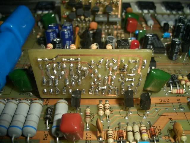
compare it to the original part....
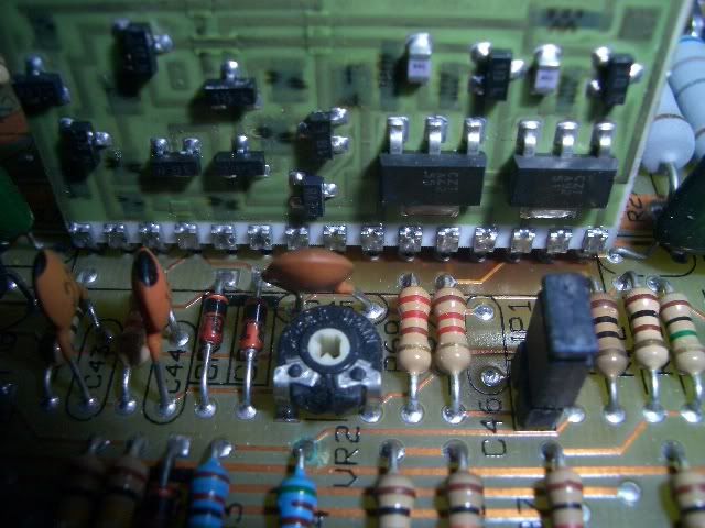
compare it to the original part....
time to resurrect this thread a bit....
I got the amp back here because there seems to be crossover distortion as the owner said it has distortion at low levels when used full range. no problems when used for subs.
when I built the amp, I used the exact same PPI circuit but after that I wasn't able to adjust bias. it was zero on both channels. it was the same (at zero) when the working channel was still using the ceramic card.
any ideas where to start? 😕 😕 😕
Do you have the bias jumpers on the headers? In one of the photos, the jumper is in place. It appears that these are older photos so I don't know what you have now.
- Status
- Not open for further replies.
- Home
- General Interest
- Car Audio
- in need of some PPI ceramic driver modules