3 days ago, I've been given 3 PPI art series amps, and they are:
1 A600.2
1 A600, and
1 AX400
However, I noticed that the ceramic driver modules are all MISSING!!
I want to revive them and need 6 driver modules.
Can anyone help me??
1 A600.2
1 A600, and
1 AX400
However, I noticed that the ceramic driver modules are all MISSING!!
I want to revive them and need 6 driver modules.
Can anyone help me??
same problem here..... for a PC2100 amp.
if all else fails, anyone got a schematic of the driver cards?
if all else fails, anyone got a schematic of the driver cards?
1moreamp had some (if I'm not mistaken) and there was another supplier in Asia. He's the one who posted the following schematic.
http://www.diyaudio.com/forums/attachment.php?s=&postid=1128157&stamp=1170949161
http://www.diyaudio.com/forums/attachment.php?s=&postid=1128157&stamp=1170949161
 Well hello boys.. I hear your having problems with itty bitty ceramic cards???
In most cases all you need to do is resolder each contact on these and they will be repaired. PPI had heat issues with these, and they tend to desolder themselves.
Now there are some secrets here:
1: do NOT use flux of any kind it attacks the pad material and the pad will never take solder again.
2: all the devices on these are commonly available, and unless your thick film resistors on the ceramic background are burnt the replacement of bad devices is a option. I have done this and it works but it takes time and patience.
3: careful about how much heat and for how long. it should just be a touch up nothing drastic involved with heat and time.
Now if you are still in need, perhaps I can get some of these below out of the build shop for you, but time is a issue here..
Attachments
i know this is a bit off topic but not too far off. i have an original Punch 45HD amp that is only putting out sound on one channel. the channel that is not putting out sound has a ceramic driver board that is getting very hot, i mean very hot! does anyone know where i can find one of these cards or does anyone think that touching up the solder points will fix the problem? there are no burned looking components and i have tested some parts on the ceramic card but not all of them yet. so far they check ok but i have a few more parts to check. any advice would help as these are neat little amps.
Contact this ebay seller for the cards.
http://search.ebay.com/_W0QQsassZdealsbyjason
The preamp/input card had a lot of problems due to leaking capacitors. Unless there was a problem with the outputs, the other cards didn't have too many problems other than broken connections on the pins (where they clipped onto the board). Use silver solder to resolder them.
1moreamp said:
Now if you are still in need, perhaps I can get some of these below out of the build shop for you, but time is a issue here..
What is the "build shop"? Does somebody actually make these now?
I just repaired a newer (2000) PPI PCX amplifier with the same problem...I thought they would have had it fixed by then!
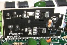
Perry Babin said:Has anyone seen this type of board in a PPI amp?
OEM or not?
Hi Perry,
I have seen these rarely, I believe firmly they are a first run card, cause they were only in very old , and early Art series amps and then never more after that.
I looked at these also before building my own, as pictured above. The device pictured in my earlier post is a replacement I and a friend redesigned to replace these older ceramic cards.
Production has not started on these yet. Offshore manufacturing had to be found as no American facility would make the 2 board run for the first 200 pieces for reasonable prices. The Proto in the pic was made on board material that cost more than a new PPI amp ever did.
Hence my statement of getting my build shop to get some of these back to me...and the issue of time...🙂
http://www.pcbfabexpress.com/index.jsp
I've used this company for several prototypes and they generally do very good work.
I think the card may have been an art series amp. I've never personally seen one. The photo was sent to me by another tech who had never seen them either.
I've used this company for several prototypes and they generally do very good work.
I think the card may have been an art series amp. I've never personally seen one. The photo was sent to me by another tech who had never seen them either.
I wonder if someone had actually tried the schematic above.
Fabricating a pcb board in my country is quite cheap, but getting the components will be a painstaking process!! Especially those tiny transistors and resistors.
Perry Babin: Thanks for the quick reply as usual 😉
1moreamp: Do you use the same schematic above? Or do you have your own revision?
Fabricating a pcb board in my country is quite cheap, but getting the components will be a painstaking process!! Especially those tiny transistors and resistors.
Perry Babin: Thanks for the quick reply as usual 😉
1moreamp: Do you use the same schematic above? Or do you have your own revision?
I was hoping for a schematic that uses normal components and thinking of making through hole replacement boards. 🙂
djQUAN said:I was hoping for a schematic that uses normal components and thinking of making through hole replacement boards. 🙂
There is a board from Lumanauw(?) that replicates the PPI, although I've never seen a schematic. You have to DL the Protel file, which have also never worked for me.
http://valveaudio.tripod.com/Upgrade.htm
I don't particularly like the through-hole mounted parts use, though.
1moreamp: Do you use the same schematic above? Or do you have your own revision?
I went back to the original circuit lay out by PPI. they knew what they were doing, and I chose not to make life hard on myself or others by re-inventing the wheel on these. In fact the pic shows all original parts and circuitry, just redesigned to compensate for the different board materials and heat related issues.
This is a Diff input and Diff output amp driver design. Much like a simple Op-amp except with Differential output.
If you chose to change this overall design, you will alter the drop in replacement of the device. The circuitry outside this device counts on this to be exactly as it is in performance, or you will be hanging stuff all over the board to get anything else to work correctly.
I tried to use the KISS principal with these, I hope you see my reasoning here...🙂
Plus most of my clients were very happy with their original PPI product and they don't want anything that may alter the overall SQ of these older amps...
EnvisionAudio said:There is a board from Lumanauw(?) that replicates the PPI, although I've never seen a schematic. You have to DL the Protel file, which have also never worked for me.
http://valveaudio.tripod.com/Upgrade.htm
I don't particularly like the through-hole mounted parts use, though.
what's wrong with using through hole? SMD isn't available here so I have no choice unless I have luck on my side that all the SMD resistor values needed are somewhere in my stack of scrap boards.
djQUAN said:
what's wrong with using through hole? SMD isn't available here so I have no choice unless I have luck on my side that all the SMD resistor values needed are somewhere in my stack of scrap boards.
Nothing is inherently wrong with through hole - I don't prefer it unless necessary. Because it's my preference, I stated my opinion. I'm sure that is OK with you, right?
I also like SMD but due to availability, I might have to settle with through hole. so, same case here. 😉
EnvisionAudio said:
There is a board from Lumanauw(?) that replicates the PPI, although I've never seen a schematic. You have to DL the Protel file, which have also never worked for me.
http://valveaudio.tripod.com/Upgrade.htm
I don't particularly like the through-hole mounted parts use, though.
EnvisionAudio: Thank you so much for pointing me out to the right direction.
I just called Mr. Lumanauw, and he told me that he no longer make those boards, however he'll be sending me the detail through email. Such a gentlemen!! I don't even know this guy, and he's willing to help me out with my problems. A lifesaver, indeed!
I should kick myself in the head, for not knowing that a genius lives 2 hours away from my home.
Once again, thank you EnvisionAudio and thank you, Mr. Lumanauw!!
I shall return soon with the update..........😀
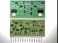
I took out the broken card today, did some measuring and compared what I got to the schematic posted by Perry.
attached is what I have.
the small signal transistors are exact parts but the BD139/140 devices are substituted for the CZTA42/92 parts.
I have made a really small through hole board about the same size as the original card but still debugging if I missed something.
attached is what I have.
the small signal transistors are exact parts but the BD139/140 devices are substituted for the CZTA42/92 parts.
I have made a really small through hole board about the same size as the original card but still debugging if I missed something.
Attachments
- Status
- Not open for further replies.
- Home
- General Interest
- Car Audio
- in need of some PPI ceramic driver modules