This shows the circuit as drawn in post #1. These are the static DC voltages for coils of 1k resistance.
Am I the only that can see at a glance that it could never work?
I see what you mean. There's a contradiction I need to resolve by measuring.
Interpreted one way, the resistors make the timing work but the switch fail. Interpreted to make the switch work, the timing fails. Something is amiss. I'll come back with definitive measurements in about 8 hours.
Here's my to-do list when I get my hands back in the preamp:
1.) Measure the resistors to get definitive values
2.) Measure the resistance of the relays
3.) Trace the entire relay circuit (including power supply and the audio side)
4.) Check for DC on the outputs
Anything else we need to resolve this impass?
1.) Measure the resistors to get definitive values
2.) Measure the resistance of the relays
3.) Trace the entire relay circuit (including power supply and the audio side)
4.) Check for DC on the outputs
Anything else we need to resolve this impass?
It's more curiosity than anything else at this stage 🙂
If the relay gives a delay before it actually does close the contact then your noises are coming from elsewhere... which comes back to trying those bleeder resistors.
Thump type noise come from very abrupt changes in DC levels being passed on to the following amplifier stages. So try the bleed resistors to see if they help.
As to the component values, well if the basic diagram is correct then it looks like that mystery resistor will be more like 680 ohms.
As to the component values, well if the basic diagram is correct then it looks like that mystery resistor will be more like 680 ohms.
I was asked what leads to the relay circuit, so I went ahead and traced the audio circuit based on the photos I have.
Do these resistor values make sense? I used the method of reading the bands that would yield 680R instead of 68K.
Note, there are already 100K bleeder resistors before and after the relay.
Also note: the schematic I posted earlier and this new schematic below are my first two attempts at tracing a circuit. so I may have presented some things a little oddly. I'm mostly self taught and quite new at this.

Last edited:
A very old fashioned obsolete way to silence the inputs.If the relay contacts are in series with the audio then the audio has to normally flow through the contacts from one side of the relay to the other. The problem with that is that any deterioration of the contacts can cause noise and non linear type distortions.
A shunt arrangement actually has the relay wired so that it shorts the audio to ground. Only when the contact open does audio get through. This arrangement takes the quality of contact out of the equation and is considered a better approach these days.
An analog switch that can handle +-15 v signal is the maxim DG419. https://www.newark.com/maxim-integr...logue-switch-single-dip-8/dp/73Y0984?st=dg419
DJ & CJ suffix can go to +-30 v, 100 ohms on resistance, and have both a NO & NC contact. So you can connect the preamp output to analog ground while switch is timing to on (NC to analog ground) and can connect preamp output to preamp input when the time is up. A CD4093 schmitt trigger can sharpen up the action of the ramp up to a snap on event.
The DG419 with DIP legs are only in farnell stock in UK, US warehouse tells me. I put dip packages on 21-4580 project board so I can solder wires to it. I put the DIP IC in beryllium copper contact DIP sockets so the IC doesn't have to withstand the heat of my amateuristic solder process. Then I wire up with 28 ga solid core wire.
If your input signal is at a large voltage, say 10, when the relay or analog switch turns on, you're going to get a pop anyway.
You might also look at biasing the op amp to avoid any DC on output with quiet input. 5534 has pins for this, requiring a 100 k pot and a 22 k series resistor to the bias pin. I don't know what dc offset control 739 has and leave it to you to look it up.
Contact pop was a very common problem in hard contact organ key switches. Hammond handled it by heavily filtering the key contact output so there weren't any high frequencies. Organs don't have high frequencies, but general music sources do. Conn used vinyl covered bus rods with a carbon core, that had a gradually decreasing resistance as the key was pushed down. These wore out in 10-20 years and are no longer available. Modern keyboards use a rubber pad under the key to decrease resistance gradually.
A device that decreases resistance gradually is the LDR, light dependent resistor. https://www.newark.com/advanced-photonix/nsl-32sr2/optocoupler-resistor-2000v/dp/71C0279?st=ldr
They take 25 ma drive current, however. The two analog sides go on one side of the barrel, the drive DC current goes on the other side. Even if your input signal is +15 v, these should not pop due to the gradually decreasing resistance. Used in professional mixers for TV and the like.
Last edited:
Despite its humble specs the uA739 was a decent sounding part for its time, likely due to its simple all class A design. The circuit you drew looks about right, though it would be more common practice for the 22K feedback resistor to connect to the transistor's emitter to include it in the feedback loop. Just something to confirm as it will work either way. Also double check the three component values at the input, i.e. is the 15K really 15K, or 1.5K. Is the 12K really 12K, or 120K. Is the 20 pF cap really 20 pF, or 200pF. As it's drawn you lose a bit over 6 dB at the input, then make it up in gain, kind of odd but they may've had a reason for it. The only other spot that jumps out is the two compensation cap values, which are likely in error. The uA739 typically required compensation values ranging from 330 pF to .1 uF. Check to see if the comp caps are actually 2 nF and 1 nF (as opposed to 20 pF and 10 pF). Other than that it looks about right, a nice piece of vintage gear (despite the sucky mute circuit). As far as the funny noises there could be one or more electrolytic caps starting to deteriorate, or the mute circuit may no longer be working in spec as you originally suspected, too fast of a turn-on, too slow of a turn off. It could even be a busted solder joint on one or more of the 100K resistors.
Okay. Here we are. The measured, double checked, accurate schematics.
The relay circuit, confirmed by measurement:

I recapped the whole preamp before trying to solve the thump issue. I discovered there are already 100K bleeder resistors on both sides of the relay (See the drawing below). I measure no DC at the outputs. The coils of th relays measure 1453 ohms, so the second spec sheet I found was correct.
So now that we know the actual values and the above, what do we make of it?
The audio circuit:

The feedback resistor does not include the transistor's emitter. Two of the questionable capacitors are disc caps marked "10" and "20J". Correct me please if I am wrong, but I believe those marks correspond to "10pF" and "20pF +/-5%". I misread the other. It is marked "1000K", so "1000pF +/- 10%"
Other errors: the resistor at the end of the positive supply is actually 22R, not 2.7K.
The relay circuit, confirmed by measurement:
I recapped the whole preamp before trying to solve the thump issue. I discovered there are already 100K bleeder resistors on both sides of the relay (See the drawing below). I measure no DC at the outputs. The coils of th relays measure 1453 ohms, so the second spec sheet I found was correct.
So now that we know the actual values and the above, what do we make of it?
The audio circuit:
The feedback resistor does not include the transistor's emitter. Two of the questionable capacitors are disc caps marked "10" and "20J". Correct me please if I am wrong, but I believe those marks correspond to "10pF" and "20pF +/-5%". I misread the other. It is marked "1000K", so "1000pF +/- 10%"
Other errors: the resistor at the end of the positive supply is actually 22R, not 2.7K.
Last edited:
You could put 2 LDR's in instead of the reed relays. Link in post 25. The part # is NSL-32s42 from Advanced Photonix. The LDR have a led in them dropping about 2.5 v. They need 20 ma in to go to 40 ohm out. They are 1 megohm off. Put the two LDR LED sides in series, minus of one to plus of the other. You could drop the emitter resistor of MPSU05 from 680 to 390 ohms to drop 10 v. You could install a new collector resistor from transistor to negative side of the two LDR's, about 1200 ohms to drop 24 volts. The two LDR drop 5 volts, the transistor drops 1 to 2 v C-E. The plus 20 rail goes to the first LDR + input. The preamp outs minus of 25 uf cap go each LDR analog side (which is a CDS cell). The outs of the two LDR analog side go to the output jack. When the MPSU05 comes on after the RC time, 20 ma flows through the two LED & turn the LDR on, softly over 5 msec.
Last edited:
You could put 2 LDR's in instead of the reed relays. Link in post 25. The LDR have a led in them dropping about 2.5 v. They need 40 ma in to go to 40 ohm out. They are 1 megohm off. Put the two LDR LED sides in series, minus of one to plus of the other. You could drop the emitter resistor of MPSU05 from 680 to 390 ohms to drop 10 v. You could install a new collector resistor from transistor to negative side of the two LDR's, about 1200 ohms to drop 24 volts. The two LDR drop 5 volts, the transistor drops 1 to 2 v C-E. The plus 20 rail goes to the first LDR + input. The preamp outs minus of 25 uf cap go each LDR analog side (which is a CDS cell). The outs of the two LDR analog side go to the output jack. When the MPSU05 comes on after the RC time, 25 ma flows through the two LED & turn the LDR on, softly.
Thank you for that very excellent suggestion, and all of them you've made along the way. If I can't get this to work, I will end up implementing it. But I want to first try preserving Hegeman's way, as I may end up reselling this at some point, and people get odd about major mods. To that end:
1.) I want to keep his 5 second startup delay, so I can either keep the 100uF cap and change the 470K resistor to 47K, or keep the 470K resistor and add a 1000uF cap. Yes? Changing the resistor seems like the better move.
2.) We now know we need 24V across 2.9K of relay coil. So 8.28mA of current. That means the emitter resistor should be 1.935K, so probably a 1.9K resistor.
Does that sound right? Any potential problem with those values I am not seeing?
The full charge time for the 25 uF cap with the 100K resistor is around 12.5 seconds. If the mute circuit energizes the relays in 5 seconds that could be an issue right there. You could try substituting (temporarily) the 25 uF caps with 4.7 uF parts to see if the problem subsides.
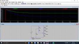
So with the new values we get this type of delay. You can see the supply voltage at the top and the two relay voltages below. Once the circuit settles there is around 12 volts across each coil. That happens around 15 seconds into the run.
Up to this point the voltage across each relay is increasing gradually, its ramping up. We can't give a definite mute time from this because it depends totally on what point the realy contact closes. For example it may gently close when there is perhaps 4 or volts across the coil, or it may need a bit more. We just don't know with certainty.
If you measure a 5 second delay in practice then that suggests the relay closes when there is around 6 volts across the coil.
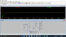
Lets look at your 25uF coupling cap situation. The only resistor value that matters is the first 100k because the second one has no impact on the settling time.
We will add to the simulation a stepped voltage and look at how the circuit settles. Lets guess and say the circuit generates an initial offset of say 6 volts and that this then falls to a final value of -0.6 volts (the emitter voltage of the final transistor. We will assume the actual circuit settles very quickly.
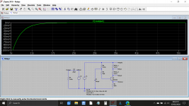
If we look closely we can see that the audio output doesn't reach 'almost' zero volts until around 15 seconds in. The scale is starting at 5 seconds in here to give better resolution.
So at 5 seconds we have a pretty large offset of over a 100mv. That will cause a massive thump if fed to a following stage like a power amp. At 15 seconds we have around 2.5 millivolts offset.
So to get a quiet delay needs the relay timing cap increasing to perhaps 680 or 820uF, however that may cause another issue because cap leakage current will become dominant in the timing circuit. The 470k doesn't pass much current and what it does pass is comparable to the cap leakage.
Up to this point the voltage across each relay is increasing gradually, its ramping up. We can't give a definite mute time from this because it depends totally on what point the realy contact closes. For example it may gently close when there is perhaps 4 or volts across the coil, or it may need a bit more. We just don't know with certainty.
If you measure a 5 second delay in practice then that suggests the relay closes when there is around 6 volts across the coil.
Lets look at your 25uF coupling cap situation. The only resistor value that matters is the first 100k because the second one has no impact on the settling time.
We will add to the simulation a stepped voltage and look at how the circuit settles. Lets guess and say the circuit generates an initial offset of say 6 volts and that this then falls to a final value of -0.6 volts (the emitter voltage of the final transistor. We will assume the actual circuit settles very quickly.
If we look closely we can see that the audio output doesn't reach 'almost' zero volts until around 15 seconds in. The scale is starting at 5 seconds in here to give better resolution.
So at 5 seconds we have a pretty large offset of over a 100mv. That will cause a massive thump if fed to a following stage like a power amp. At 15 seconds we have around 2.5 millivolts offset.
So to get a quiet delay needs the relay timing cap increasing to perhaps 680 or 820uF, however that may cause another issue because cap leakage current will become dominant in the timing circuit. The 470k doesn't pass much current and what it does pass is comparable to the cap leakage.
Attachments
In that case, the purchaser should enjoy a authentic historic loud pop at relay timeout.as I may end up reselling this at some point, and people get odd about major mods.
My mixer thumps at power on. There is no silence circuit. I deal with it by first turning on the mixer, then turning on the power amp, then turning on the radio or other sound source. I turn the radio off first, then the power amp, then the mixer.
Per Mooly's analysis & kaos suggestion, I see no problem with decreasing 25 uf cap from 739 to relay to 4.7 uf NP. Increasing timer cap would cause the circuit to shorten timeout in a few years as timer cap leakage builds up. It may quickly get to a point to where it doesn't ever turn on.
Allen 300 organ had a silence circuit like this between power amp & speaker. At 33 years the cap got leaky and it stopped passing music at all. After cap replacement, at 37 years the relay contact got dirty and stopped passing music at all. I cleaned it with a file, it worked a year then at 38 years the relay contact got dirty again. I've deleted this troublesome relay an d connected the speaker direct, which thumps at turn on and whistles at turn off. The new church paid $400 to move the free organ and just deals with the imperfect behavoir. Their old vacuum tube organ used to occasionally motorboat rudely at 40 thumps/sec for seconds at a time. Once I get all the 38 year old electrolytic caps replaced I may put a RG Keen dual nfet disconnect series each speaker.
Last edited:
- Home
- Amplifiers
- Power Supplies
- Improving Very Simple Time Delay Circuit