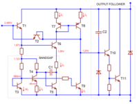
Bob Cordell's book calls the circuit in post #19 a "ring of two". To ensure the circuit doesn't start up in the (stable!) state Iq1=Iq2=zero nanoamperes, Bob moves the multi megohm resistor, and connects it from collector to emitter of one of the transistors.
Well, Bob Cordell's book seems to indicate that the 2-transistor feedback CCS (fig 2.14a) is superior to the green LED current source (fig 2.12c) which is at odds with Walter Jung's article. Does anybody have an explanation?
I never encountered such CSS components. Any commercial or diy amp featuring them ?
I seem to remember a certain T2 (or Noir) amp I built that had an E-153 current regulating diode...
25v max, 15mA and cost about $1USD. They can also be temperature compensated with a parallel resistor.
Noir, a two transistor headphone amp: class-A, single ended, 150mA bias
https://au.mouser.com/datasheet/2/362/P22-23-CRD-1729293.pdf
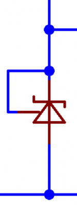
BJT based constant current sources:
The effect of not having a gradient of zero in the Veb versus Vec transfer characteristic can be reduce by using higher value emitter resistors. These will require a higher bias voltage for the current source. Instead of using two signal diodes to create a "quasi" stable bias voltage, one can use prefacricated voltage regulators like the 78* series and change the value of the emitter resistor to allow the required current. This arrangement forces any potential increases in Ic to cause more voltage drop across the emitter resistor which becomes more difficult to happen.
The effect of not having a gradient of zero in the Veb versus Vec transfer characteristic can be reduce by using higher value emitter resistors. These will require a higher bias voltage for the current source. Instead of using two signal diodes to create a "quasi" stable bias voltage, one can use prefacricated voltage regulators like the 78* series and change the value of the emitter resistor to allow the required current. This arrangement forces any potential increases in Ic to cause more voltage drop across the emitter resistor which becomes more difficult to happen.
Last edited:
Correction of error on post #25:
The line should read: The effect of not having a gradient of zero in the Ic versus Vec transfer characteristic...
The effect of not having a gradient of zero in the Veb versus Vec transfer characteristic...
The line should read: The effect of not having a gradient of zero in the Ic versus Vec transfer characteristic...
Well, Bob Cordell's book seems to indicate that the 2-transistor feedback CCS (fig 2.14a) is superior to the green LED current source (fig 2.12c) which is at odds with Walter Jung's article. Does anybody have an explanation?
Walt Jung published measurement of real circuits. I doubt that Bob Cordell had time to measure himself every circuit published in his book. Most likely theoretical values or LTSpice simulation results were used for most. As models are far from ideal, that explains difference and why he has provided own models for BJTs used for his designs.
I had recently LTSpice calculate PSRR of 160 dB while I measured 117 dB at the actual circuit.
That could be part of the problem. Walt Jung quotes a 45Kohm output impedance for the 2-transistor circuit, whereas Bob Cordell says it's an 'impressive 3Mohm'. That's a pretty large difference between the two authors.
Another 'issue' is Ohm law. 😀
When comparing CCS impedance or PSSR it is important that comparison takes in the account current through CCS. Decreasing CCS current by factor 10 will increase its impedance by the same factor or PSRR by 20 dB.
When comparing CCS impedance or PSSR it is important that comparison takes in the account current through CCS. Decreasing CCS current by factor 10 will increase its impedance by the same factor or PSRR by 20 dB.
I never encountered such CSS components. Any commercial or diy amp featuring them ?
They've been used in Japanese amps since the 70s but for a long time they were unavailable.
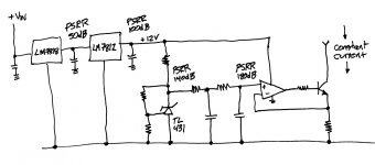
The straightforward way to improve CCS PSRR is to stop trying to make a "simple" circuit, and instead embrace an obvious tradeoff: bigger parts-count gives bigger PSRR. Cascading several filtering stages increases PSRR.
For people who worry about temperature effects: use bandgap reference ICs whose tempco has been carefully nulled by experts. Voltage regulator ICs, shunt voltage reference ICs, that sort of thing. Here is an illustrative example:
_
For people who worry about temperature effects: use bandgap reference ICs whose tempco has been carefully nulled by experts. Voltage regulator ICs, shunt voltage reference ICs, that sort of thing. Here is an illustrative example:
_
Attachments

I never encountered such CSS components. Any commercial or diy amp featuring them ?
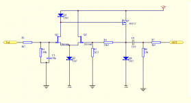
Somewhere on this site I found a schematic purporting to be the Threshold FET2 preamp by Nelson Pass. It features three current regulating diodes from the Siliconix J500 line. Linear Systems still makes and sells the J500 series of CRDs today, here is their datasheet
_
Attachments
They've been used in Japanese amps since the 70s but for a long time they were unavailable.
There was a modification scheme ("Tu-be or not tu-be"?)for the Dynaco tube preamp from that era that used CRDs in place of the 12AX7 plate resistors. I had one and enjoyed it right up to the point that it blew up.
I've just measured the AC impedance of a two transistor feedback current source near identical to Walter Jung's Figure 3A but running at 5 mA. Came in at 14.87 k ohm which correlates reasonably well with Walt's 45k ohm for a his 2mA. I have seen Bob Cordell's 3Mohm figure given elsewhere for this circuit so was a little surprised. I think perhaps Bob's figure wasn't measured but was simulated but may be wrong. My solution for improvement, which I (also?) have yet to measure, was using Walt's figure 5A but adding two further Green LED's in series and replacing his Rset with a 2mA CCS. As a result R1 is no longer influencing the set current to anything like the same degree. I was lucky to have had the voltage headroom for this and this is not really a good solution for higher currents or when there simply isn't the voltage headroom. My rough calculations are that this solution gives approx. 1.4Mohm output z.Well, Bob Cordell's book seems to indicate that the 2-transistor feedback CCS (fig 2.14a) is superior to the green LED current source (fig 2.12c) which is at odds with Walter Jung's article. Does anybody have an explanation?
If you want lowest CCS noise as well as line regulation then you might be wise to stick with LED's or diodes for the biasing as they have much lower noise than the Bandgap references. Also you can improve the AC performance a little without adding a CCS for R1 by splitting the R1 into two halves and adding a capacitor from their junction to the +ve rail.
John
Last edited:
- Home
- Amplifiers
- Solid State
- Improving simple CCS PSRR by 30 dB