
Steen,
The test is somewhat involved and this is the way I have done it,
You will need a signal gen with sinuous output tuned to a frequency that your RMS voltage meter can read (check with the specs of the meter, this is AC voltage of course) usually the test is carried at 1k frequency but if its too high for the meter you can do with lower frequencies. BTW the test could also be done with an oscope with the advantage of seeing that you are not clipping the signal.
Set the signal gen at about 1 or 2 V RMS and connect to the input of the pre with the attenuator wide open. Next, check the output of the pre with the voltmeter (no load) and adjust the signal gen to give 10V RMS at the output (assuming the pre is capable of this voltage without clipping).
Without changing the above settings add a dummy load to the output of the pre with a known resistance, say 5K and measure the voltage at the output again.
Now we have two values, a no load and a loaded one. The second voltage will be lower than the no load value. With these to voltages and the known load resistor we are able to calculate the output impedance of the pre.
If there are no EE’s around to help me on the way to calculate this I’ll have to dig the info and post later, sorry for this, its been a long time since I did this measurements and cant remember from top of my hat.
The same measurements can be done at different attenuator settings to see how do they change.
😎
Wow, thanks Tony! Pretty good from top of your hat, indeed🙂 I will have to pass though, since I dont have a tone gen. Maybe someone else can do the measurements? I cant be the only one with a X-box? sorry X-BoZ.
Steen🙂
Steen🙂
Go to this site and check output impedance for the way to calculate
http://www.mitedu.freeserve.co.uk/Theory/inzoz.htm
http://www.mitedu.freeserve.co.uk/Theory/inzoz.htm
steenoe said:Wow, thanks Tony! Pretty good from top of your hat, indeed🙂 I will have to pass though, since I dont have a tone gen. Maybe someone else can do the measurements? I cant be the only one with a X-box? sorry X-BoZ.
Steen🙂
With so many amps you build you should be gearing up friend!!!
If you are capable of building these amp I'm quite sure you know Ohms law, add to this a couple of (used and cheep) instruments which are easy to use and you are all set up.
No offence of course 🙂
apassgear said:If there are no EE’s around
Tony,
you're not an EE ?
Shocking

....................................................(
 )
)
jacco vermeulen said:
Tony,
you're not an EE ?
Shocking
....................................................(
Thanks God....heheheh
regarding post 595........
Papa- if you read this, I have question:
What is -in your opinion- of more benefit ( or less consequence):
place caps on diff outputs , or
place caps on diff inputs ?
if we presume that we can find both size-smaller and bigger ones - in same quality...........
ps. I don't need any power xformer ,but if you are willing to share few dozens of tiny jfet critters...............or-even better - some dusty toob OPTs.........please-in quartets only
Ordinarily I recommend taking the feedback on such a circuit before the output capacitor to avoid problems.
I generally use input capacitors to avoid turn-on thumps in the field where I don't know what the source is going to look like.
People do get excited about capacitors, but I find that if you use quality devices, it's not much of a problem.
😎
I generally use input capacitors to avoid turn-on thumps in the field where I don't know what the source is going to look like.
People do get excited about capacitors, but I find that if you use quality devices, it's not much of a problem.
😎
Nelson Pass said:Ordinarily I recommend taking the feedback on such a circuit before the output capacitor to avoid problems.
I generally use input capacitors to avoid turn-on thumps in the field where I don't know what the source is going to look like.
People do get excited about capacitors, but I find that if you use quality devices, it's not much of a problem.
😎
while you are at keyboard side ........(even if you are usually invisible on list ).....
in that case is wise to implement few pots for offset setting.....
I'm OK with choosed currents?
edit:
you just hit No. 600 in this thread.......
and.....which toob xformers you found ?
Holy schmoley, look away for a day and several new pages go by!
OK, where was I? Right! In my last post, I made a rather large goof. I got my gain and output swing numbers from an old sim I had on my work computer, but didn't notice that it had the feedback network values altered. The maximum output swing numbers are still correct, but the gain numbers are wrong. My circuit has roughly 13dB of gain, and the Twisted circuit is running roughly 12dB.
So to answer Steen, from the Twisted schematic, change R18 and R19 to 100k for 19dB (9x) gain. Also, you are correct that the preamp negative output needs to be grounded when driving a single ended amplifier input. If at all possible, the output should be grounded right at the circuit out, before the volume attenuator. This still leaves 20dB of feedback in the circuit, so I think that should be OK. Give that a try and I think you'll find a rather significant improvement. It should now be able to drive the F4 to about 35W(rms) output. If that still leaves something to be desired, let me know, I have some other possibilities up my sleeve.
On the subject of circuit redesign to get that sweet JFET sound, I'll focus on ways to refit existing X-BoSoz's, mostly beause it looks like Zen Mod has the "build a new one from scratch" side of the topic well under control. The other reason I'll keep to the simple modifications is that Nelson has previously stated that the cascode device adds little of its own character to the sound, so it doesn't seem overtly necessary to change those. It should be possible to swap in 2SK170's for Q4 and Q5 in the Twisted schematic, but we'll have to lower the current down from the 40mA per device we were running before. That will also require that we will also have to change R1, R2, R6, and R7. If we set for 10mA per device, then these resistors should change to 6k, and we can now use 1/2W resistors. R8 in the CCS will now be ~110R to get 20mA total bais for 10mA per device.
I'm doing this redesign on the fly and in a hurry, so someone should check my work, cause I haven't had time to proof my work. Oh yeah, remember that the pinouts are different between the IRF610 and 2SK170!
Gotta run,
Terry
None taken. I really should invest in some more equipment, like a scope and a tonegenerator.apassgear said:
With so many amps you build you should be gearing up friend!!!
If you are capable of building these amp I'm quite sure you know Ohms law, add to this a couple of (used and cheep) instruments which are easy to use and you are all set up.
No offence of course 🙂
Very nice work.Zen Mod said:I'm I wrong...................or I'm wrong...........
Steen🙂
metalman said:Holy schmoley, look away for a day and several new pages go by!
OK, where was I? Right! In my last post, I made a rather large goof. I got my gain and output swing numbers from an old sim I had on my work computer, but didn't notice that it had the feedback network values altered. The maximum output swing numbers are still correct, but the gain numbers are wrong. My circuit has roughly 13dB of gain, and the Twisted circuit is running roughly 12dB.
So to answer Steen, from the Twisted schematic, change R18 and R19 to 100k for 19dB (9x) gain. Also, you are correct that the preamp negative output needs to be grounded when driving a single ended amplifier input. If at all possible, the output should be grounded right at the circuit out, before the volume attenuator. This still leaves 20dB of feedback in the circuit, so I think that should be OK. Give that a try and I think you'll find a rather significant improvement. It should now be able to drive the F4 to about 35W(rms) output. If that still leaves something to be desired, let me know, I have some other possibilities up my sleeve.
On the subject of circuit redesign to get that sweet JFET sound, I'll focus on ways to refit existing X-BoSoz's, mostly beause it looks like Zen Mod has the "build a new one from scratch" side of the topic well under control. The other reason I'll keep to the simple modifications is that Nelson has previously stated that the cascode device adds little of its own character to the sound, so it doesn't seem overtly necessary to change those. It should be possible to swap in 2SK170's for Q4 and Q5 in the Twisted schematic, but we'll have to lower the current down from the 40mA per device we were running before. That will also require that we will also have to change R1, R2, R6, and R7. If we set for 10mA per device, then these resistors should change to 6k, and we can now use 1/2W resistors. R8 in the CCS will now be ~110R to get 20mA total bais for 10mA per device.
I'm doing this redesign on the fly and in a hurry, so someone should check my work, cause I haven't had time to proof my work. Oh yeah, remember that the pinouts are different between the IRF610 and 2SK170!
Gotta run,
Terry
Thanks Terry. All nice suggestions. I will make the changes to the Twisted sometime this weekend, and see how it performs.
The J-fet modifications also sounds interesting. Is any changes in the supply voltages needed? I am not sure how many volts Q4 and Q5 see's.
Steen🙂
steenoe said:
Very nice work.
Steen🙂
tnx. I already told you.......even when I scribe something ditto from my head , result always remind me on Aleph..........I'm anxious
but-what is even more surprising,at least for me ' is fact that I really don't need any of them.........preamp or amp.......
😎 but it is so big fun learning
hehe......this days I'm using one little ECL82 SE amp........that's pure joy.......
steenoe said:
..............
The J-fet modifications also sounds interesting. Is any changes in the supply voltages needed? I am not sure how many volts Q4 and Q5 see's.
Steen🙂
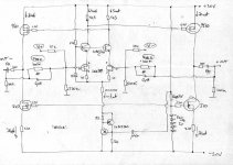
post exact schmtc and I'll try to re-draw it for ya 🙂
Zen Mod said:
post exact schmtc and I'll try to re-draw it for ya 🙂
Thats very kind of you, indeed. Once we have a finished roadmap, I am all set to test it.
The schematic was posted here:
http://www.diyaudio.com/forums/showthread.php?postid=1193716#post1193716
What do you think of my new avatar😉
Steen🙂
steenoe said:
Thats very kind of you, indeed. Once we have a finished roadmap, I am all set to test it.
The schematic was posted here:
http://www.diyaudio.com/forums/showthread.php?postid=1193716#post1193716
Steen🙂
I'll see...today or tomorrow
What do you think of my new avatar😉
I like it......but-even if you like listen the blues.......you are one happy camper......not real bluesman.....
and I'm glad for that
edit-tell me voltage of d1 in your schmtc , V+ and V-
editedit -steen - if you ever decide to build this "new" jfet schmtc ,I'll draw toob rectification and shunt regs for ultimate version...........hehe - which will last max 6 months at your place
No need to hurry, take your time.Zen Mod said:
I'll see...today or tomorrow
I like it......but-even if you like listen the blues.......you are one happy camper......not real bluesman.....
and I'm glad for that
edit-tell me voltage of d1 in your schmtc , V+ and V-
editedit -steen - if you ever decide to build this "new" jfet schmtc ,I'll draw toob rectification and shunt regs for ultimate version...........hehe - which will last max 6 months at your place
Voltage of zener D1 is 6,8V.
Positive rail is 60V, negative rail is 20V.
Unforunately, I never made any tube-stuff.
Steen🙂
steenoe said:
No need to hurry, take your time.
Voltage of zener D1 is 6,8V.
Positive rail is 60V, negative rail is 20V.
Unforunately, I never made any tube-stuff.
Steen🙂
tnx . noted
tube stuff.............you will...at least susy preamp .....in best forum tradition - it'll be named Death of All Papa's Preamps .......DoAPP
- Status
- Not open for further replies.
- Home
- Amplifiers
- Pass Labs
- Improving on X-BosoZ to mate the F4